CFP 2/4/8 ZONE FIRE ALARM CONTROL PANEL installation & maintenance manual Approved Document No.
CFP ALARMSENSE 2/4/8 ZONE FIRE ALARM PANEL CONTENTS EN54 Compliance Statement ..............................................................................................................3 Basic Overview & Key Features ..........................................................................................................3 Important Notes ..................................................................................................................................4 The Fire Panel Enclosure ..........
CFP ALARMSENSE 2/4/8 ZONE FIRE ALARM PANEL EN54 COMPLIANCE STATEMENT Relevant standards: EN54 Part 2 (Fire detection and fire alarm systems, control and indicating equipment) EN54 Part 4 (Fire detection and fire alarm systems, power supply equipment). ! EN54-2 EN5 54-2 54 2 Please note, some of the engineering functions provided on the panel go beyond the scope of EN54 Part 2. A caution symbol (left) is used to indicate where such a function is non-compliant with EN54-2.
CFP ALARMSENSE 2/4/8 ZONE FIRE ALARM PANEL IMPORTANT NOTES This equipment must only be installed and maintained by a suitably skilled and technically competent person. THIS EQUIPMENT IS A PIECE OF CLASS 1 EQUIPMENT AND MUST BE EARTHED. Items supplied with this panel • Installation & Maintenance Manual (i.e. this manual). Explains how to install, commission and maintain the fire alarm control panel. This manual must not be left accessible to the User. • User Manual / Log Book.
CFP ALARMSENSE 2/4/8 ZONE FIRE ALARM PANEL THE FIRE PANEL ENCLOSURE The panel is supplied with a plastic detachable lid, a plastic back box and a minimum of two separate PCBs. The relative location of these PCBs is indicated in figure 1 below. The panel can be surface or semi-flush mounted. It must be sited indoors in an area not subject to conditions likely to affect its performance, e.g. damp, salt-air, water ingress, extremes of temperature, physical abuse, etc.
CFP ALARMSENSE 2/4/8 ZONE FIRE ALARM PANEL FIRST FIX All system wiring should be installed to meet BS 5839 Part 1 and BS 7671 (Wiring Regulations). Other national standards of installation should be used where applicable. Cable types and limitations Consult Clause 26 of BS 5839 Part 1: Fire detection and fire alarm systems for buildings - code of practice for system design, installation, commissioning and maintenance, for detailed information on cables, wiring and other interconnections.
CFP ALARMSENSE 2/4/8 ZONE FIRE ALARM PANEL Fixing the base to the wall Using the five mounting holes provided (see figure 3 below), fix the base securely onto/into the wall. The mounting holes are suitable for use with No.8-10, or 4-5mm countersunk screws. Assess the condition and construction of the wall and use a suitable screw fixing. Any dust or swarf created during the fixing process must be kept out of the fire alarm panel and care must be taken not to damage any wiring or components.
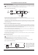
CFP ALARMSENSE 2/4/8 ZONE FIRE ALARM PANEL Typical sounder circuit wiring Four conventional sounder circuits are available on the fire alarm panel. These are designed for use with conventional sounders and bells only. AlarmSense™ sounders should not be used on these conventional sounder circuits (use these on the AlarmSense™ zone circuits instead, see page 7).
CFP ALARMSENSE 2/4/8 ZONE FIRE ALARM PANEL Typical auxiliary output wiring Two auxiliary open collector outputs and one auxiliary output connections are available on the panel, as detailed below: Reset Output (RESET) Turns on during the panel’s reset cycle. Can be used for resetting fire alarm system devices such as roller-shutter doors or beam detectors. This output remains active for approximately one second after all other outputs have returned to normal.
CFP ALARMSENSE 2/4/8 ZONE FIRE ALARM PANEL SECOND FIX Connecting the panel Connecting the panel’s internal connections and PCBs should be undertaken immediately before commissioning. Before you begin, we recommend you check all devices on the detector and sounder circuits are correctly connected (see pages 7 and 8) and that cable integrity is verified throughout the installation. Important: DO NOT use a high voltage insulation tester with any electronic devices connected.
CFP ALARMSENSE 2/4/8 ZONE FIRE ALARM PANEL Figure 8 : Power Supply PCB layout and Mains connection details Incoming Mains cable must be segregated from other cables and should only enter the panel through either of these drill outs. Good quality cable glands must always be fitted. CONN1 L N L N PSU earth strap Do not operate the panel without this strap connected. CONN1 PRIMARY FUSE F1 L = Live; N = Neutral; FUSE 1ATH 250V HRC = Earth.
CFP ALARMSENSE 2/4/8 ZONE FIRE ALARM PANEL Installing the Main Control PCB The panel’s Main Control PCB provides all the connections for the system’s detector circuits, sounder circuits, auxiliary inputs and auxiliary outputs. It also provides the engineer with access to a wide range of engineering functions, details of which appear later in this manual.
CFP ALARMSENSE 2/4/8 ZONE FIRE ALARM PANEL Connecting the detector and sounder circuits Incoming detector and sounder circuits should be connected to the relevant connector block on the Main Control PCB as shown in figure 11 below. For typical detector and sounder circuit wiring diagrams, please refer to pages 7 and 8.
CFP ALARMSENSE 2/4/8 ZONE FIRE ALARM PANEL PROGRAMMING THE PANEL An overview of the panel’s controls Three control levels are available on the panel - general user (access level one), authorised user (access level two) and engineer (access level three), as detailed below: General user controls (access level one) When the panel is in its normal state, the indicator lights on the panel front give a comprehensive overview of the system’s current status.
CFP ALARMSENSE 2/4/8 ZONE FIRE ALARM PANEL Important note: If link PLK1 is fitted on the Main Control PCB (see right) triggering a manual call point on any zones programmed for coincidence will activate the alarm sounders and outputs immediately. (Alarms from detectors will still be processed as described previously in this section). PLK1 MCP/SOUNDER FUNCTION From an installation point of view, detectors on zones assigned for coincidence should be installed in close proximity to each other.
CFP ALARMSENSE 2/4/8 ZONE FIRE ALARM PANEL Accessing the engineer controls Before programming the panel, please refer to pages 14 and 15 for an overview of the various engineering functions available and the effect their implementation will have on the way the system operates. To gain access to the panel’s engineer functions, remove the panel lid using the Torx key provided and press the ACCESS LEVEL THREE FUNCTIONS button on the Main Control PCB (see figure 12 below).
CFP ALARMSENSE 2/4/8 ZONE FIRE ALARM PANEL To program non-latching zones (Note: This function is non-compliant with EN54-2) 1. 2. 3. 4. 5. 6. ! EN54-2 EN5 N5 54-2 54 2 Press the ACCESS LEVEL THREE FUNCTIONS button until the NONLATCHING light flashes (any zones that are already programmed for non-latching operation will now have their Zone Fault lights lit steady).
CFP ALARMSENSE 2/4/8 ZONE FIRE ALARM PANEL FAULT DIAGNOSIS Fault indications When a fault occurs on a critical part of the fire alarm system, the panel responds by activating its internal sounder and illuminating the General Fault light and any other Fault light(s) relating to the fault. The panel’s fault output will also activate (provided it has not been disabled). The type of faults typically indicated at the fire alarm panel are highlighted below.
CFP ALARMSENSE 2/4/8 ZONE FIRE ALARM PANEL 1.1 Zone faults • To find out if a head out fault has occurred on a detector zone: 1. Remove the panel’s lid using the Torx key provided and press the ACCESS LEVEL THREE FUNCTIONS button on the Main Control PCB to gain access to the panel’s engineer functions (see below). CFP ALARMSENSE PANEL CONTROLS SYSTEM FAULT REPEATER FAULT HEAD OPEN SHORT OUT CIRCUIT CIRCUIT SOUNDER STATUS SW8 DELAYS COINCIDENCE ACCESS LEVEL THREE NONLATCHING FUNCTIONS 2.
CFP ALARMSENSE 2/4/8 ZONE FIRE ALARM PANEL • The battery fuse (F2) is ruptured. Symptoms: The panel runs on Mains, but not on batteries. Suggested actions: 1. Isolate the Mains supply and disconnect the batteries. 2. Remove the Main Control PCB and check the battery fuse (F2) on the Power Supply PCB for continuity. 3. If ruptured check the Power Supply and Main Control PCBs for signs of damage.
CFP ALARMSENSE 2/4/8 ZONE FIRE ALARM PANEL 1.3 System faults System faults are unique in that they do not automatically clear when rectified. Three different types of system fault can occur; watchdog fault, site memory corruption fault or PLL (phase lock loop) fault. • To find out which type of system fault has occurred: 1.
CFP ALARMSENSE 2/4/8 ZONE FIRE ALARM PANEL 1.4 Repeater faults • To find out which of the repeater panels are faulty: 1. Remove the panel’s lid using the Torx key provided and press the ACCESS LEVEL THREE FUNCTIONS button on the Main Control PCB to gain access to the panel’s engineer functions (see below). CFP ALARMSENSE PANEL CONTROLS REPEATER FAULT SYSTEM FAULT HEAD OPEN SHORT OUT CIRCUIT CIRCUIT SOUNDER STATUS SW8 DELAYS COINCIDENCE ACCESS LEVEL THREE NONLATCHING FUNCTIONS 2.
CFP ALARMSENSE 2/4/8 ZONE FIRE ALARM PANEL STANDBY BATTERY CALCULATION GUIDE The standby time of the fire alarm panel, after the Mains has failed, depends on the quiescent loading of the panel, the alarm load of the panel, and the capacity of the batteries. To determine the capacity of batteries required for any given standby period, the following formula should be used: Standby Time in Ah = 1.25 x [(TxA) + H x (P+Z)] The multiplier 1.
CFP ALARMSENSE 2/4/8 ZONE FIRE ALARM PANEL TECHNICAL SPECIFICATION POWER SUPPLY SPECIFICATION Mains supply voltage 230V 50/60Hz Mains rated current 350mA maximum Internal power supply Total output current limited to 19V - 28.5V (27V nominal). Ripple 7V maximum (battery fault) 1.5A @ 230Vac (ImaxA = 146mA) Maximum internal battery resistance Ri max = 1.