
Product specifications


CFP ALARMSENSE 2/4/8 ZONE INSTALLATION & MAINTENANCE MANUAL • Approved Document No. DFU7002020 Rev 1 • Page 10 of 24
C
FP ALARMSENSE 2/4/8 ZONE FIRE ALARM PANEL
SECOND FIX
C
onnecting the panel
Connecting the panel’s internal connections and PCBs should be undertaken immediately before commissioning.
Before you begin, we recommend you check all devices on the detector and sounder circuits are correctly
connected (see pages 7 and 8) and that cable integrity is verified throughout the installation.
Important: DO NOT use a high voltage insulation tester with any electronic devices connected.
Faults occurring in the wiring which are not picked up at this stage will almost certainly result in spurious and
intermittent faults when the equipment is energised.
Installing the Power Supply PCB
T
he panel’s Power Supply PCB combines the functions of a Mains to dc switched mode power supply unit, battery
charging unit and battery monitoring unit.
WHEN CONNECTED, THE POWER SUPPLY PCB STORES VOLTAGES AT UP TO 400Vdc AND MAY BE
LETHAL IF TOUCHED. DO NOT TOUCH THE PCB WHILST THE RED ‘HAZARDOUS VOLTAGES PRESENT’
LIGHT IS LIT.
Under no circumstances should the fire alarm panel be operated without the Power Supply PCB correctly mounted
in the panel’s enclosure and the three retaining screws securely tightened.
The PCB should be positioned in the panel as shown in figure 8 on page 11.
Connecting the Mains
The general requirement for the Mains supply to this equipment is described on page 6.
DO NOT attempt to connect Mains to the panel until you are fully conversant with the layout and features of the
Power Supply PCB, as described above and in figure 8 on page 11.
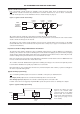
The incoming Mains cable should be brought into the panel at the top right hand side of the enclosure and
terminated at the connector block (CONN1) on the Power Supply PCB.
Make sure the Mains earth wire is connected directly to this connector block and NOT to the secondary base earth
post which is provided for making off detector and sounder circuit screens.
The Power Supply PCB’s earth strap MUST be connected to the spade on the chassis earth post
before operation. The spade is compressed against a shoulder on the post via the lowest nut.
The earth post may appear loose, this is intended by design.
Connecting the standby batteries
Two new, good quality and fully charged 12V valve regulated lead acid (VRLA) batteries are required as the
emergency standby power supply for the panel. Caution: DO NOT use any other type of batteries due to the risk
of explosion.
The batteries should be connected in series and located in the panel’s enclosure as shown in figure 9 on page 11.
The battery leads, link wire and nylon cable ties are supplied in the panel’s accessory pack. Run the battery leads
through the slits in the panel’s lower plastic ribs and secure the batteries into position using the nylon cable ties
as shown.
The panel’s sophisticated battery monitoring unit protects the batteries against deep discharge by activating a cut
off circuit when the standby supply voltage reaches 21V approx. If batteries are not fitted, are discharged or in
poor condition, a PSU fault will show at the fire alarm panel.
The capacity of the batteries used will depend upon the required standby time. To calculate the batteries required
for any given standby period, please refer to the calculation guide on page 23.
Always dispose of used batteries in accordance with the battery manufacturer’s instructions.