
Product specifications

Installing the Main Control PCB
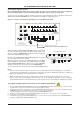
The panel’s Main Control PCB provides all the connections for the system’s detector circuits, sounder circuits,
auxiliary inputs and auxiliary outputs. It also provides the engineer with access to a wide range of engineering
functions, details of which appear later in this manual.
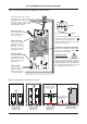
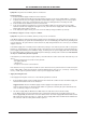
Before any connections can be made, the Main Control PCB must first be securely positioned inside the fire alarm
panel (see figure 10 below) using the five retaining screws. As the PCB is presented to the panel, remember to
attach the telecoms-style connecting cable to SKT2 on the reverse of the Main Control PCB and to PL1 on the Power
S
upply PCB.
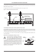
Important: SKT1 on the reverse of the Main Control PCB is for the connection of optional system expansion devices
such as Network Driver Cards (for repeater panels) and Relay Output Boards. If any of these devices are to be used,
r
efer to the individual installation instructions supplied with them as they will need to be fitted to the panel before
the Main Control PCB.
All of the 5mm connector blocks located across the top of the PCB can be removed to aid installation. Take care
w
hen reconnecting them that you do so the correct way round. We recommend that you clearly label all system
wiring to reduce the likelihood of incorrect connection.
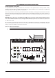
Figure 10 : Main Control PCB layout
CFP ALARMSENSE 2/4/8 ZONE INSTALLATION & MAINTENANCE MANUAL • Approved Document No. DFU7002020 Rev 1 • Page 12 of 24
C
FP ALARMSENSE 2/4/8 ZONE FIRE ALARM PANEL
SW4
S
W3
SW8
SW1
SW2
CONN2
S
W7
SW6
SW5
ACCESS
LEVEL THREE
FUNCTIONS
OPEN
CIRCUIT
DELAYS TEST
ACCESSEDTEST
PSU
FAULT
Z
2Z3
GENERAL
FAULT
DELAY MINUTES
0
1
2
3
CAUTION - RISK OF EXPLOSION IF
INCORRECT TYPE OF BATTERIES FITTED.
DISPOSE OF USED BATTERIES ACCORDING
TO THE MANUFACTURERS INSTRUCTIONS.
4
NONLATCHING
5
6
7
FAULT
OUTPUT
STATUS
SUPPLY
OK
REMOTE
OUTPUT
AUX
OUTPUT
STATUS
FOR OPERATIONAL DETAILS PLEASE
CONSULT THE MAINTENANCE MANUAL
Z
4
COINCIDENCE
Z
5Z6 Z7
8
REPEATER
FAULT
SHORT
CIRCUIT
S
ILENCE
INTERNAL
S
OUNDER
OUTPUTS
DELAYED
SOUNDER
STATUS
R
EMOTE
OUTPUT
STATUS
GENERAL
DISABLEMENT
GENERAL
F
IRE
9
10
SYSTEM
FAULT
NEXT OPTION
CODE ENTRY(3)
ENABLE/DISABLE
LAMP TEST
CODE ENTRY(4)
C
ODE ENTRY(1)
CODE ENTRY(2)
ESCAPE ACCESS
SILENCE/
R
ESOUND
S
OUNDERS
RESET
FAULT
Z
ONE1
Z
ONE4
Z
ONE2
Z
ONE3
Z
ONE8
Z
ONE7
Z
ONE6
Z
ONE5
FIRE
VR1
–
+
–
+
–
+
–
+
–
+
–
+
+
4
CS3CS2CS8Z
CC
STUPNI
STIUCRIC REDNUOSOUTPUTS
AUX
AUX
2
4V
0
V
ALT
REM
CONN5
CONN6
CONN7
CONN8
CONN9
–
+
–
–
+
–
+
–
+
Z
1
DETECTOR CIRCUITS
REMOVING THIS CIRCUIT
B
OARD EXPOSES HAZARDOUS
VOLTAGES - PLEASE REFER TO
INSTALLATION INSTRUCTIONS
WARNING
S
ENSITIVE TO STATIC
ELECTRICITY - OBSERVE
PRECAUTIONS BEFORE
HANDLING
I
O
ACCESS LEVEL 2
RST
FAULT
NO
NC
C
NO
NC
C
1
CS
+
–
HEAD
OUT