
Product specifications

1.1 Zone faults
• To find out if a head out fault has occurred on a detector zone:
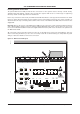
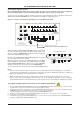
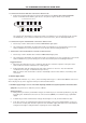
1. Remove the panel’s lid using the Torx key provided and press the ACCESS LEVEL THREE FUNCTIONS
button on the Main Control PCB to gain access to the panel’s engineer functions (see below).
2. Continue pressing the ACCESS LEVEL THREE FUNCTIONS button until HEAD OUT light pulses.
Any existing Zone Fault lights are suppressed and the zone light(s) for any zone(s) with a head out fault
are illuminated, e.g. if a detector head has been removed on zone 2, Zone 2’s Fault light will be lit.
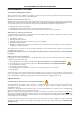
• To find out if an open circuit fault has occurred on a detector zone:
1. Follow steps 1 and 2 outlined above until the OPEN CIRCUIT light pulses.
2. Any existing Zone Fault lights are suppressed and the zone light(s) for any zone(s) with an open circuit
fault are illuminated, e.g. if the wiring on zone 6 is broken, Zone 6’s Fault light will be lit.
• To find out if a short circuit fault has occurred on a detector zone:
1. Follow steps 1 and 2 detailed above until the SHORT CIRCUIT light pulses.
2. Any existing Zone Fault lights are suppressed and the zone light(s) for any zone (s) that have a short circuit
fault are illuminated, e.g. if the wiring on zone 4 has been shorted, Zone 4’s Fault light will be lit.
Suggested actions:
1. Disconnect the faulty detector zone completely and refit the end-of-line capacitor at the panel. If the
fault condition clears this confirms there is a wiring fault.
2. Refit and double check the wiring and the end-of-line capacitor on the zone. Trace the fault with
consideration for the type of fault indicated (see above).
Note: A common short circuit fault is a detector head badly seated in a base which is not making a true
connection.
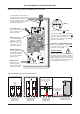
1.2 Power supply faults
A power supply fault indicates one, or more, of the following faults. Page 11 of this manual must be referenced
when carrying out any of the suggested action procedures described below.
• The Mains supply voltage is too low or has failed completely, the Mains fuse (F1) has ruptured or the PSU has failed.
Symptoms: The panel runs on batteries, but not on Mains.
Suggested actions:
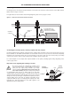
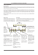
1. Taking all due precautions, check Mains voltages are within range (see Technical Specifications, page 24)
by probing Live and Neutral connections at connector block (CONN1). If not within range, repair Mains
supply.
2. If within range and the red Hazardous Voltages Present light is not lit, check the Mains fuse (F1).
3. If the fuse is intact, the red Hazardous Voltages Present light on the Power Supply PCB may, or may not,
be lit. The PSU is faulty and should be replaced. Isolate the Mains supply and wait for the red Hazardous
Voltages Present light to extinguish before replacing the Power Supply PCB.
C
FP ALARMSENSE 2/4/8 ZONE FIRE ALARM PANEL
CFP ALARMSENSE 2/4/8 ZONE INSTALLATION & MAINTENANCE MANUAL • Approved Document No. DFU7002020 Rev 1 • Page 19 of 24
D
ELAYS
TEST
NONLATC HIN G
COINCIDENCE
A
CCESS
L
EVEL THREE
F
UNCTIONS
OPEN
C
IRCUIT
SHORT
C
IRCUIT
REPEATER
F
AULT
SYSTEM
F
AULT
S
W8
C
FP ALARMSENSE PANEL CONTROLS
H
EAD
O
UT
SOUNDER
STATU S