KI51PV-754 Copyright All rights are reserved. No part of this publication may be reproduced, transmitted, transcribed, stored in a retrieval system or translated into any language or computer language, in any form or by any means, electronic, mechanical, magnetic, optical, chemical, manual or otherwise, without the prior written permission of the company. Brands and product names are trademarks or registered trademarks of their respective companies.
KI51PV-754 nVIDIA® nForce4 C51PV & MCP51 Supports Socket 754 AMD® AthlonTM 64/ SempronTM Processor (The power consumption for the aforementioned processors must be rated at 65W or less.
Things You Should Know 0 The images and pictures in this manual are for reference only and may vary from the product you received depending on specific hardware models, third party components and software versions. 0 This mainboard contains very delicate IC chips. Always use a grounded wrist strap when working with the system. 0 Do not touch any IC chip, lead, connector or other components.
Table of Contents CHAPTER 1. GETTING STARTED .................................................... 1 INTRODUCTION ....................................................................................................... 1 SPECIFICATION ....................................................................................................... 2 CONFIGURATION .................................................................................................... 5 Layout of KI51PV-754 (Right Side).......................
Mainboard KI51PV-754 Chapter 1. Getting Started Introduction ® Congratulations on choosing the KI51PV-754 Mainboard. It is based on the nVIDIA nForce4 C51PV Northbridge chipset and the nVIDIA® nForce4 MCP51 Southbridge chipset; with TM 64/ possessing integrated graphics feature. The mainboard supports the AMD Athlon TM Sempron processor (The power consumption for the aforementioned processors must be rated at 65W or less.) socket 754 with FSB (Front Side Bus) frequencies of 800 MHz (1600 MT/s).
Mainboard KI51PV-754 Specification CPU: z Supports Socket 754 TM TM z Supports AMD Athlon 64/ Sempron Processor (The power consumption for the aforementioned processors must be rated at 65W or less.
Mainboard KI51PV-754 IDE Connector: z Two IDE connectors, support up to four IDE devices can be set z Supports Ultra ATA 66/100/133 z Supports high capacity hard disk drives Serial ATA II Connector: z Four SATA II connectors, support up to four SATA II HDDs can be set z Supports SATA 2.
Mainboard KI51PV-754 BIOS: z Phoenix-Award™ BIOS z Supports APM 1.2 z Supports ACPI 2.
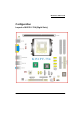
Mainboard KI51PV-754 Configuration Layout of KI51PV-754 (Right Side) 5
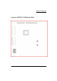
Mainboard KI51PV-754 Layout of KI51PV-754 (Back Side) 6
Mainboard KI51PV-754 Hardware Installation This section will assist you in quickly installing your system hardware. Wear a wrist ground strap before handling components. Electrostatic discharge may damage your system components. CPU Processor Installation TM TM This mainboard supports AMD Athlon 64/ Sempron processor using Socket 754. Before building your system, we suggest you visit the AMD website and review the processor installation procedures. http://www.amd.
Mainboard KI51PV-754 FAN Headers: CPUFAN, CHASFAN There are two fan headers available for cooling fans. The cooling fans play an important role in maintaining ambient temperatures in your system. The CPUFAN header is attached with a CPU cooling fan. The CHASFAN header is attached with other cooling fans. 1 CPUFAN/ CHASFAN Pin 1 2 3 Assignment Ground Power (+12V) FAN RPM rate sense Attention You can avoid damaging your CPU due to high temperatures with proper cooling equipment.
Mainboard KI51PV-754 2. Align a memory on the socket such that the notch on the memory matches the break on the socket. 3. Lower the memory vertically into the socket and press firmly by using both thumbs until the memory snaps into place. 4. Repeat steps 1, 2 & 3 for the remaining memory and DIMM sockets setup. * The pictures shown above are for reference only. The actual installation may vary depending on models.
Mainboard KI51PV-754 PS/2 Mouse & PS/2 Keyboard Ports: KB/MS This mainboard provides a standard PS/2 mouse port and a PS/2 keyboard port. The pin assignments are described below. Pin Assignment Pin Assignment 1 Data 4 +5 V (fused) 2 N/A 5 Clock 3 Ground 6 N/A DVI & VGA Connectors: DVI, VGA The mainboard provides one DVI connector and one VGA connector on the back panel of the computer case.
Mainboard KI51PV-754 Audio Ports: Sound This mainboard provides three audio ports, the Mic-in, Line-in and Line-out. These are the standard audio ports that provide basic audio function. Line-In (Blue) This port is for audio input and connects to external audio devices such as CD player, tape player, etc. When the Super 5.1 Channel Audio Effect is enabled, this port will output audio for the rear speakers. Line-Out (Green) This port is an output audio port used for connecting to speakers or a headset.
Mainboard KI51PV-754 SATA II Connector: SATA1/SATA2/SATA3/SATA4 The four SATA II connectors support 3 Gbps transmit rate and RAID 0/1/ 0+1/ JBOD/ 5 mode. One SATA II connector only can attach one SATA II HDD of each time using SATA cables. 1 SATA1~4 Pin 1 3 5 7 Assignment Ground TXRXGround Pin 2 4 6 Assignment TX+ Ground RX+ This mainboard supports RAID 0/1/0+1/JBOD/5 modes, refer Appendix II for more information.
Mainboard KI51PV-754 Hard Drive LED Header (Red): HD_LED If your case front panel has a hard drive LED cable, attach it to this header. The LED will flicker when there is hard disk drive activity. Reset Switch Header (Blue): RST_SW This header can be attached to a momentary SPST switch (reset button) cable on your case front panel. The switch is normally left open. When the switch closed, it will cause the mainboard to reset and run the POST (Power-On Self Test).
Mainboard KI51PV-754 Attention If you are using a USB 2.0 device with Windows 2000/ XP, you will ® need to install the USB 2.0 driver from the Microsoft website. If you ® are using Service pack 1 (or later) for Windows XP, and using Service pack 4 (or later) for Windows® 2000, you will not have to install the driver. TV OUT Header: TV_OUT Attach the TV OUT cable (Optional) which the product provided onto this header.
Mainboard KI51PV-754 Serial Interface Header: COM1/COM2 This mainboard provides two COM headers for you to connect external serial connectors on the back panel of your case. Attaching the serial connector cables (Optional) onto these two headers, then you can use the serial connectors to attach with a mic, modem or other peripheral devices.
Mainboard KI51PV-754 USB Power Selection Header: JP2 USB devices attached to USB ports of the back panel can awaken the system from sleep mode. In order to enable this functionality, you must adjust the jumper caps on JP2 header for +5V or +5VSB mode depending on which USB port that the USB device is attached to.
Mainboard KI51PV-754 Audio Configuration SPDIF Header: SPDIF (Optional) S/PDIF is a recent audio transfer file format, which provides high quality audio using optical fiber and digital signals. This mainboard is capable to deliver audio output and receive audio input through a SPDIF Card (Optional) with this header attached. You can just simply set the SPDIF Card on your case back panel, and attach the SPDIF cord and FRONT AUDIO cord onto specific headers on the mainboard.
Mainboard KI51PV-754 Pin 1 3 5 7 9 Assignment Mic in/center Mic_VREF Front out_R N/A Front out_L FRONT AUDIO Pin Assignment 2 Ground 4 Audio power +5V 6 Rear out_R 8 Key 10 Rear out_L Slots PCI Slot: PCI1 PCI stands for Peripheral Component Interconnect, which is a bus standard for installing expansion cards such as network card, SCSI card, etc. to these PCI slots.
Mainboard KI51PV-754 Power Supply Attachments ATX Power Connector: ATX_PWR, ATX_12V This mainboard provides two ATX power connectors, a 24-pin ATX_PWR connector and a 4-pin ATX_12V connector. You must use a power supply that has both of these connectors and both connectors must be attached before the system is powered on. These power connectors support several power management functions such as the instant power-on function. The connector pins are described below.
Mainboard KI51PV-754 Chapter 2. BIOS Setup Introduction This section describes PHOENIX-AWARD™ BIOS Setup program which resides in the BIOS firmware. The Setup program allows users to modify the basic system configuration. The configuration information is then saved to CMOS RAM where the data is sustained by battery after power-down. The BIOS provides critical low-level support for standard devices such as disk drives, serial ports and parallel ports.
Mainboard KI51PV-754 Main Menu When you enter the PHOENIX-AWARD™ BIOS Utility, the Main Menu will appear on the screen. The Main menu allows you to select from several configuration options. Use the left/right arrow keys to select a particular configuration screen from the top menu bar or use the down arrow key to access and configure the information below.
Mainboard KI51PV-754 Main Menu Setup Configuration Options Item Options Description Set the system date. Note that the ‘Day’ automatically changes when you set the date. Date mm dd yyyy Time hh: mm: ss Set the current time of the system. IDE Primary Master Options contained in sub menu. Press to enter the sub menu. IDE Primary Slave Options contained in sub menu. Press to enter the sub menu. IDE Secondary Master Options contained in sub menu.
Mainboard KI51PV-754 Advanced BIOS Features Removable Device Priority Select removable device boot priority. Hard Disk Boot Priority Select hard disk drive boot priority. First /Second/Third Boot Device Select the order in which devices will be searched in order to find a boot device.
Mainboard KI51PV-754 Virus Warning This option allows you to choose the Virus Warning feature for IDE Hard Disk boot sector protection. If this function is enabled and a program attempts to write data into this area, BIOS will display a warning message on the screen and sound an audio alarm (beep). Options: Disabled (Default), Enabled CPU Internal Cache Make CPU internal cache active or inactive. System performance may degrade if you disable this item.
Mainboard KI51PV-754 APIC stands for Advanced Programmable Interrupt Controller, and is used to extend the number of available IRQs available in order to avoid sharing conflicts. Options: Disabled, Enabled (Default). MPS Version Control For OS The 1.1 version is the older version that supports 8 more IRQs in the Windows NT environment. Choose the new 1.4 version for Windows 2000 and Windows XP. Options: 1.4 (Default), 1.1.
Mainboard KI51PV-754 Options: Auto, 2T, 3T (Default), 4T, 5T, 6T, 7T Row precharge Time (Trp) You can set the Row precharge time. Precharge to Active or Auto-Refresh of the same bank. Options: Auto, 2T, 3T (Default), 4T, 5T, 6T, 7T 1T/2T Memory Timing Use this option to select the memory timing. Options: 1T, 2T (Default) Frame Buffer Size This option allows you to set for pure DOS mode of using. You can set the amount of value to share main memory.
Mainboard KI51PV-754 CPU Speed Detected This option displays the default CPU speed. CPU Host Frequency (MHz) This option displays the CPU Host frequency. You can set it from 200 to 450. The default depends on your CPU frequency and the CPU installed. CPU Spread Spectrum The Spread Spectrum function can reduce the EMI (Electromagnetic Interference) generated for CPU.
Mainboard KI51PV-754 This option displays the result of your HT Ratio setting between Northbridge chipset and Southbridge chipset HT Spread Spectrum The Spread Spectrum function can reduce the EMI (Electromagnetic Interference) generated for Hyper Transport. Options: Disabled, Center (Default), Down PCIE Clock This option allows you to select PCIE clock form 100 Mhz (Default) to 145Mhz.
Mainboard KI51PV-754 Init Display First With systems that have multiple video cards, this option determines whether the primary display uses a PCI slot or a PCI-E slot. Options: PCI Slot, Onboard, PCIEx. IDE Function Setup If you highlight the “IDE Function Setup” label and then press the enter key, it will take you to a submenu with the following options. OnChip IDE Channel 0/1 The mainboard chipset contains a PCI IDE interface with support for two IDE channels.
Mainboard KI51PV-754 SATA1/2 Primary/ Secondary RAID This allows you to enable or disable the RAID function for the SATA1/2 Primary/Secondary device. Options: Enabled, Disabled (Default) Serial-ATA 1/2 This item allows you to enable or disable the SATA1/2 device. Options: Enabled (Default), Disabled.
Mainboard KI51PV-754 Hot Key Power ON This option allows you to use the Ctrl key along with a hot key (function key) to power on your system. This option is configurable only when “Power-On Function” is set to “Hot Key”. Options: Ctrl-F1 (Default), Ctrl-F2, ……, Ctrl-F12. Onboard FDC Controller Select “Enabled” if your system has a floppy disk controller (FDC) installed on the system board and you wish to use it. If you install an add-in FDC or the system has no floppy drive, select “Disabled”.
Mainboard KI51PV-754 Power Management The Power Management Setup Menu allows you to configure your system to utilize energy conservation features as well as power-up/ power-down options. ACPI Suspend Type The item allows you to select the suspend type using the ACPI operating system. Options: S1 (POS) (Default) Power on Suspend S3 (STR) Suspend to RAM S1 & S3 POS and STR Power Management There are three options of Power Management: 1. Min.
Mainboard KI51PV-754 When this option is enabled, each of the ranges is from 1 minute to 1 hour except for HDD Power Down, which ranges from 1 minute to 15 minute and includes a “disable” option. Note: If you select Min. or Max. Power Saving modes, the “HDD Power Down” value will be fixed. User Define, Min Saving, Max Saving Video Off Method This option determines the manner in which the monitor goes blank. Options: Blank Screen This option only writes blanks to the video buffer.
Mainboard KI51PV-754 You can choose which date of the month the system will boot up. This option is configurable only when “RTC Wake Up” is set to “Enabled”. (Min=0 Max=31) Time (hh: mm: ss) Alarm You can choose the hour, minute and second the system will boot up. This option is configurable only when “RTC Wake Up” is set to “Enabled”. K8 Cool’n’Quiet Control When this option is set to “Auto”, the system will auto control the CPU voltage and frequency depends the loading of system.
Mainboard KI51PV-754 Load System Default Settings Load System Default Settings. Load System Turbo Settings Load System Turbo Settings. Load CMOS From BIOS Load defaults from flash ROM for systems without batteries. Save CMOS To BIOS Save defaults to flash ROM for systems without batteries. Exit Menu Save & Exit Setup Save all configuration changes to CMOS (memory) and exit setup. A confirmation message will be displayed before proceeding.
Mainboard KI51PV-754 Chapter 3: Software Setup Software List Category Platform ® Windows 2000 /XP Microsoft DirectX 9.0c ® Windows 2000 /XP nForce Chipset Driver ® Windows 2000 /XP nForce Display Driver ® Windows 2000 /XP nVIDIA Firewall ® Windows 2000 /XP Realtek AC’97 Audio Driver ® Windows 2000 /XP Marvell LAN Driver Software Installation Place the Driver CD into the CD-ROM drive and the Installation Utility will auto-run.
Mainboard KI51PV-754 z z z z z z Microsoft DirectX9.0c – provides the software of Microsoft DirectX 9.0c. nForce Chipset Driver – provides all the drivers needed for the chipset. nForce Display Driver – provides the driver of Integrated GeForce Graphics Engine. nVIDIA Firewall – provides firewall to protect your system from hackers and viruses. Realtek AC’97 Audio Driver – provides the driver of Realtek AC’97 Audio CODEC.
Mainboard KI51PV-754 Chapter 4: Troubleshooting Problem 1: No power to the system. Power light does not illuminate. Fan inside power supply does not turn on. Indicator lights on keyboard are not lit. Causes: 1. Power cable is unplugged. 2. Defective power cable. 3. Power supply failure. 4. Faulty wall outlet; circuit breaker or fuse blown. Solutions: 1. Make sure power cable is securely plugged in. 2. Replace cable. 3.Contact technical support. 4.
Mainboard KI51PV-754 Problem 4: System only boots from the CD-ROM. The hard disk can be read and applications can be used but booting from the hard disk is impossible. Causes: Hard Disk boot sector has been corrupted. Solutions: Back up data and applications files. Reformat the hard drive. Re-install applications and data using backup disks. Problem 5: Error message reading “SECTOR NOT FOUND” displays and the system does not allow certain data to be accessed.
Mainboard KI51PV-754 Problem 10: Keyboard failure. Causes: Keyboard is disconnected. Solutions: Reconnect keyboard. Replace keyboard if you continue to experience problems. Problem 11: No color on screen. Causes: 1. Faulty Monitor. 2. CMOS incorrectly set up. Solutions: 1. If possible, connect monitor to another system. If no color appears, replace monitor. 2. Call technical support. Problem 12: The screen displays “C: drive failure.” Causes: Hard drive cable not connected properly.
Mainboard KI51PV-754 Appendix I: Super 5.1 Channel Audio Effect Setup Channels Setup 1. After starting your system, click the Sound Effect Manager icon from the tool bar on the desktop. You can also find the icon by going to Start-> Setting -> Control Panel. 2. Click the Speaker Configuration button. One of the screens will display as shown below. 3. You can choose a 2, 4 or 6 channel (speaker) system. 2 Channels 4 Channels 6 Channels Super 5.
Mainboard KI51PV-754 Appendix II: RAID Setup Introduction to RAID RAID (Redundant Array of Independent Disks) technology is a sophisticated disk management system that manages multiple disk drives. It enhances I/O performance and provides redundancy in order to prevent the loss of data in case of individual disk failure. The RAID facility on this board provides RAID 0, RAID 1, RAID 0+1, RAID JBOD, and RAID 5. Disk Striping (RAID 0) Striping is a performance-oriented, non-redundant disk storage technology.
Mainboard KI51PV-754 2. The “RAID config” option for enabling RAID will be found on the “Peripherals” screen as part of the “IDE Function Setup” section shown as below-left (Peripherals >> IDE Function Setup >> RAID config). Arrow down to the IDE RAID item and press enter. 3.On the “RAID config” screen (shown below-right), enable the disks that you want to use as RAID disks (in this example there are four SATA hard drives configured as RAID disks).
Mainboard KI51PV-754 Channel 1 – Represents one of the SATA connectors Controller 0 – 1st connector (e.g. PATA1 or SATA1) Controller 1 – 2nd connector (e.g. PATA2 or SATA2) Master/Slave – SATA drives will always be Master drives since an SATA connector can only support 1 drive. PATA connectors can support a Master and a Slave drive. For Example: On a board with 4 connectors (PATA1, PATA2, SATA1, SATA2), the following applies: 0.0.M = PATA1 (master drive) 0.0.S = PATA1 (slave drive) 0.1.
Mainboard KI51PV-754 Next, in the “Free Disks” section, you can use the up/down arrow keys to select disks to be used in your RAID array. After highlighting a disk, use the right-arrow key to activate the disk as part of the RAID Array. The selected disk will move over to the “Array Disks” section. You can use the left-arrow key to reverse your selection. After you finish selecting all your disks, Press . A confirmation message will display as shown below.
Mainboard KI51PV-754 RAID 1 mode (Array List) RAID 1 mode (Array Detail) Deleting an Array You can delete an existing array on the “Array Detail” screen. Press the key. A warning/confirmation message will display (as shown below). Press to confirm.
Mainboard KI51PV-754 After the array is successfully deleted, the screen will display as shown below. Rebuilding a RAID Mirrored Array This section applies to Mirrored, Striped Mirroring RAID and RAID 5 configurations and describes how to reestablish the integrity of a mirrored environment after replacing one of the drives (typically because of a single disk failure).
Mainboard KI51PV-754 Before you rebuild a RAID Mirrored Array Before you begin rebuilding a RAID Mirrored Array, you must copy the “NvRaidMan.exe” file from the bundled CD Driver to your C: drive. [CD File Location Path => D: \ Driver \ nForce \ 6.53 \ IDE \ WIN2K (or WINXP)\ NvRaidMan.exe] To rebuild a mirrored array, bring up the NVIDIA RAID Utility. From the “Array List” screen, select the array with the newly installed drive. Then go to the “Array Detail” screen (press Enter).
Mainboard KI51PV-754 Install the OS of Windows® 2000/XP into your RAID HDDs ® In this section, it will tell you how to install the operating system of Windows 2000/XP into your RAID drives. The installation steps below will assume that your HDDs have already been attached to either the PATA or SATA connectors, and also your BIOS RAID Utility has already been configured (see NVIDIA BIOS RAID Utility Configuration section).
Mainboard KI51PV-754 Appendix III: ABS (Albatron BIOS Security) Card Setup Introduction The ABS (Albatron BIOS Security) system provides your system with a recovery BIOS backup when your onboard BIOS has been damaged beyond system boot capability. Preparation and Setup You should prepare a boot floppy disk and have it ready in case of such BIOS failures. Otherwise you will have to find another computer to make the boot floppy disk from.
Mainboard KI51PV-754 Place the boot floppy disk (from the “Preparation and Setup” section) into the floppy drive and turn on your system. Note: If your system is not setup to use the floppy drive as the first boot drive, you must enter the BIOS setup utility and make the appropriate adjustments. During the initial boot up sequence the screen will display a message that will give you an opportunity to enter the BIOS setup utility (typically, “Press Delete Key to enter BIOS utility”) .
Mainboard KI51PV-754 8. The initial AWARD BIOS FLASH screen (shown below-left) will appear and prompt you with the message, “Do you want to save BIOS?” Type “N” (Note: Typing “Y” is only used when saving the BIOS from the onboard BIOS to the floppy disk). Type N Type Y The next screen (shown above-right) will display a message “Press ’Y’ to Program or ‘N’ to Exit”. Then type ‘Y’ to begin the onboard BIOS flash procedure. 9.
Mainboard KI51PV-754 10. During the next boot sequence, enter the BIOS utility program (Note: During the boot sequence you will be given a chance to enter the BIOS utility by pressing the “DEL” key on most systems). Load the system with the default settings, and save the changes before exit the BIOS utility program. Then the onboard BIOS recovery procedures are completed at this time. Follow the path: Defaults -> Load System Default Settings -> Y .
Mainboard KI51PV-754 11. After you have recovered your onboard BIOS, you can choose to remove or not remove the ABS Card from the mainboard. If you do choose to remove the ABS Card from the mainboard, make sure that the system is powered off before you remove the card. After you remove the ABS card you must replace the two jumper caps on the BIOSCN1 header back to the default positions (pins 1-2 and pins 3-4 are both closed as shown).