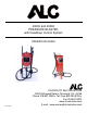
40000 and 40002 PRESSURE BLASTER with Deadman Control System OPERATION GUIDE DIVISION OF S&H INDUSTRIES 5200 Richmond Road Cleveland, OH 44146 Phone 216-831-0550 Toll Free 800-253-9726 Fax 216-831-9573 www.shindustries.com E-mail: www.service@shindustries.com Rev.
40000 & 40002 Assembly Instructions Page 2 WARNING! Do not use an ALC Pressure Blaster until you have read this manual and you understand its contents and warnings. These warnings are included for the health and safety of the operator and those in the immediate vicinity. Keep this manual for future reference.
40000 & 40002 Assembly Instructions Page 3 ASSEMBLY INSTRUCTIONS NOTE: Refer to diagrams on pages 14 and 15 when assembling. 1. Attach wheel assemblies to wheel support as shown in inset #1 (p. 15). Do not tighten nut snugly against wheel hub, as some movement is required to allow free rolling of wheels. Tighten hex nut directly against wheel support housing to lock wheel assembly in place. 2. Abrasive regulator valve has been preassembled and attached to the bottom of the tank.
0000 & 40002 Assembly Instructions Page 4 PRESSURE BLASTER SAFETY PROCEDURES CAUTION: READ THESE SAFETY PROCEDURES IN THEIR ENTIRETY – PARTS OF THE OPERATING INSTRUCTIONS ARE WITHIN THESE WARNINGS. These procedures are not intended to be exhaustive due to the many variables in the abrasive blasting field. Therefore, we INSIST that the hands, ears, mouth, nose and eyes be covered with appropriate safety protection at all times. ADDITIONAL WARNINGS! CAUTION MUST BE EXERCISED BY USER AT ALL TIMES 1.
40000 & 40002 Assembly Instructions Page 5 8. Drain air out of tank through the inlet valve and disconnect power before maintenance cleaning of any kind. When removing nozzle, caution must be exercised as air pressure may still be in the hose if the nozzle is plugged. 9. For safe operation, perform recommended preventive maintenance on blaster tank, remote unit and accessories. Replace all worn parts before they fail. Immediate replacement of worn components is required.
40000 & 40002 Assembly Instructions Page 6 OPERATING INSTRUCTIONS OPERATING TECHNIQUE: 1. Connect air hose to air inlet valve. Manufacturer recommends using minimum incoming air hose of 1/2” I.D. Using an air hose smaller than 1/2” I.D. will restrict air volume and result in poor unit operation. Prior to injection of air, be certain air inlet valve and nozzle valve are in the OFF position. With Deadman Valve closed and closure plug in the UP position, open air inlet valve allowing air to pressurize.
40000 & 40002 Assembly Instructions Page 7 WARNING! All persons except for the equipment user must stay clear of the blast machine. The user may pressurize or depressurize the machine at any time. The noise generated by the sudden release of compressed air while the machine is pressurized or depressurized may startle bystanders, and may vent abrasive under pressure. Either condition could result in injury. NOZZLE SELECTION CHART PART NO. NOZZLE I.D. CFM PSI BLASTING AREA ABRASIVE SQ. FT./MIN. USAGE/HR.
40000 & 40002 Assembly Instructions Page 8 AIR COMPRESSOR RECOMMENDATION: To permit efficient operation of your air compressor, follow these guidelines: 1. Use a smaller size nozzle and air jet to control the demand of air. 2. Do not blast continuously. Stop blasting operation periodically to allow the compressor to cool. No compressor is designed to constantly run at full RPM. Use 70% of the rated output. 3. Use a minimum 1/2” air hose or metal piping from your air compressor to the blaster.
40000 & 40002 Assembly Instructions Page 9 Warning! Do not fill the pressure vessel to within six (6) inches of the top of the vessel. If a hose is accidentally disconnected during use media spray may occur.
40000 & 40002 Assembly Instructions Page 10 TROUBLESHOOTING TIPS PROBLEM/CAUSE POSSIBLE SOLUTION Surging of blast flow: Air pressure too low Too much media Check air pressure gauge on compressor Adjust media valve 40200 Excessive media consumption: Media valve open too far Air pressure too low Close slightly Check pressure gauge on compressor Clogging and plugging of blast flow: Debris in media Media size too large Nozzle plugs Nozzle plugs Wet media Purge and screen Use smaller grit size Use larger
40000 & 40002 Assembly Instructions Page 11 MAINTENANCE WARNING! Failure to observe the following before performing any maintenance could cause serious injury or death from the sudden release of compressed air: Depressurize the blast machine. Disconnect power supply. Lockout and tagout the compressed air supply. Bleed the air supply line to the blast gun. Immediate replacement of worn components is required.
40000 & 40002 Assembly Instructions Page 12 Note: Replace with genuine ALC parts – do not substitute. ITEM NO. 1 2 3 4 5 6 7 8 9 10 11 12 13 14 15 16 17 18 19 20 PART NO. 40224 40219 40221 40213 40198 40186 10935 10937 40217 40199 40192 10905 40223 40170 40196 40193 Pg. 4 40164 40165 40168 DESCRIPTION PARTS LIST ITEM NO.
40000 & 40002 Assembly Instructions Page 13
40000 & 40002 Assembly Instructions Page 14
40000 & 40002 Assembly Instructions Page 15 Disclaimer of Warranties. S & H Industries, Inc. ("Seller") makes no warranties with respect to any goods delivered to Buyer or users except as specifically set forth within this manual. S & H INDUSTRIES, INC. MAKES NO IMPLIED WARRANTIES OF MERCHANTABILITY OR FITNESS FOR A PARTICULAR PURPOSE WITH RESPECT TO ANY OF THE GOODS, AND S & H INDUSTRIES, INC. EXPRESSLY DISCLAIMS ANY IMPLIED WARRANTIES AGAINST INFRINGEMENT. S & H INDUSTRIES, INC.