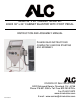
40402 36” x 24” CABINET BLASTER 40403 36” x 24” CABINET BLASTER WITH FOOT PEDAL INSTRUCTION AND ASSEMBLY MANUAL PLEASE READ INSTRUCTIONS COMPLETELY BEFORE STARTING ANY ASSEMBLY DIVISION OF S&H INDUSTRIES 5200 Richmond Road Cleveland, OH 44146 Phone 216-831-0550 Toll Free 800-253-9726 Fax 216-831-9573 www.shindustries.com E-mail: www.service@shindustries.com Rev.
40402 & 40403 Assembly Instructions Page 2 WARNING! Do not use an ALC Cabinet Blaster until you have read this manual and you understand its contents and warnings. These warnings are included for the health and safety of the operator and those in the immediate vicinity. Keep this manual for future reference.
40402 & 40403 Assembly Instructions Page 3 CABINET OPERATION 1. Assemble light and siphon gun/foot pedal per instructions. 2. Attach gloves to inner glove hole collar and secure with glove clamps included in parts kit. 3. Remove dust collector hose from bottom of drum and connect one end to the dust collector and the other end to the right upper side of cabinet. 4. Plug light and dust collector electric cords into your 110 volt, 60 cycle electric line. 5.
0402 & 40403 Assembly Instructions Page 4 If twist-on type air hose couplings are used, they must be secured by safety lock pins or wires to prevent accidental disconnection while under pressure. Hose disconnection while under pressure could cause serious injury. CABINET BLASTER SAFETY PROCEDURES CAUTION: READ THESE SAFETY PROCEDURES IN THEIR ENTIRETY – PARTS OF THE OPERATING INSTRUCTIONS ARE WITHIN THESE WARNINGS.
40402 & 40403 Assembly Instructions Page 5 7. Do not use this equipment in any area that might be considered hazardous or where flammable gases or liquids are present. Failure to do so may cause an explosion resulting in serious injury. AIR COMPRESSOR RECOMMENDATION: To permit efficient operation of your air compressor, follow these guidelines: 1. Use a smaller size nozzle and air jet to control the demand of air. 2. Do not blast continuously.
40402 & 40403 Assembly Instructions Page 6 MAINTENANCE Check siphon gun nozzle and air jet for wear when replacing. Proper matching of nozzle and air jet is very important for effective blasting. Match size or color small/small (gold), medium/medium (silver) and large/large (black). Replace media when worn or excessive dusting occurs. Check and clean dust collector and filter frequently.
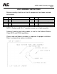
40402 & 40403 Assembly Instructions Page 7 LIGHT ASSEMBLY INSTRUCTIONS Before assembly check to see that all components have been received with cabinet. Part No. 11007 11008 11009 11010 11011 Qty. Description 1 1 1 1 1 Light fixture Power cord Switch Electrical box Box cover Part No. 11012 11014 11013 11160 11161 Qty. 1 1 1 2 4 Description Power cord connector ¾’’ Sheet Metal Plug Wire nut 8-32 x 1/2” machine screw 8-32 hex nut NOTE: Gasket and 8-32 x 1” machine screws are in light assembly.
40402 & 40403 Assembly Instructions Page 8 LIGHT ASSEMBLY INSTRUCTIONS 1. Press metal plug into 3/4” diameter hole from inside of cabinet. (The purpose of the grommet is to prevent abrasion of the light wires.) 2. Install electrical box to outside of cabinet using two 8-32 x 1/2” machine screws and two 8-32 hex nuts. Holes in box and cabinet are prepunched. NOTE: Use one of the machine screws to secure ground wire (green wire) to back of box.
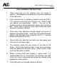
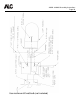
40402 & 40403 Assembly Instructions Page 9 ASSEMBLY DIAGRAM FOR BLAST CABINET Below is the component breakdown for ALC Cabinet Blasters. Please see separate instructions and parts breakdowns for light assembly, siphon gun/foot pedal and dust collector. Item No. 1 2 3 4 5 5 5 6 6 Part No.
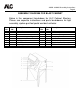
40402 & 40403 Assembly Instructions Page 10 Use maximum 60 watt bulb (not included)
40402 & 40403 Assembly Instructions Page 11 OPTIONAL SIPHON GUN/FOOT PEDAL ASSEMBLY INSTRUCTIONS Below is the component breakdown for siphon gun/foot pedal. Part No.
40402 & 40403 Assembly Instructions Page 12 must be kept open and clear of any debris for proper operation.
40402 & 40403 Assembly Instructions Page 13
40402 & 40403 Assembly Instructions Page 14 SIPHON GUN PARTS BREAKDOWN Replacement Parts and Optional Accessories PART NO.
40402 & 40403 Assembly Instructions Page 15 ASSEMBLY DIAGRAM FOR DUST COLLECTOR Below is the component breakdown for ALC 100 CFM dust collector. The dust collector is assembled and ready for use. Dust collector hose is located in the bottom drum of the collector and must be removed and attached to dust collector and cabinet. Item No. 1 1 2 3 3 4 5 Part No. 11568 10759 11637 11012 11008 40267 SM Description Cap for dust collector Protective edging Switch Connector Electric cord Filter bag n/a Item No.
40402 & 40403 Assembly Instructions Page 16 TROUBLESHOOTING TIPS PROBLEM/CAUSE POSSIBLE SOLUTION Surging of blast flow: Air pressure too low Check pressure gauge on air compressor Excessive media consumption: Air pressure too low Check pressure gauge on air compressor Clogging and plugging of blast flow: Debris in media Media size too large Nozzle plugs Wet media Moisture in abrasive media: Wet media Water in air Purge and screen Use smaller grit size Use larger nozzle and correct Dry media, drain w
40402 & 40403 Assembly Instructions Page 17 Coal Slag #40093 Coal Slag is used when paint and rust has to be removed from steel, such as car bodies, tanks or heavy machinery. Coal Slag is faster cutting, can be re-used, is moisture free, and will not pack or absorb moisture. (25 Lb. container) Steel Grit #40109 Steel grit is extremely fast cutting on rusty metal and hard to remove paint. Steel Grit is popular because it leaves a very smooth finish.
40402 & 40403 Assembly Instructions Page 18 Disclaimer of Warranties. S & H Industries, Inc. ("Seller") makes no warranties with respect to any goods delivered to Buyer or users except as specifically set forth within this manual. S & H INDUSTRIES, INC. MAKES NO IMPLIED WARRANTIES OF MERCHANTABILITY OR FITNESS FOR A PARTICULAR PURPOSE WITH RESPECT TO ANY OF THE GOODS, AND S & H INDUSTRIES, INC. EXPRESSLY DISCLAIMS ANY IMPLIED WARRANTIES AGAINST INFRINGEMENT. S & H INDUSTRIES, INC.