
Use and Care Manual


40402 & 40403 Assembly Instructions
Page 9
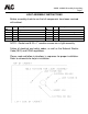
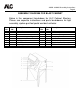
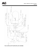
ASSEMBLY DIAGRAM FOR BLAST CABINET
Below is the component breakdown for ALC Cabinet Blasters.
Please see separate instructions and parts breakdowns for light
assembly, siphon gun/foot pedal and dust collector.
Item
No.
Part
No.
Description
Item
No.
Part
No.
Description
1
11635
Window frame
6
11161
8-32 hex nut
2
40251
Window lens
7
40248
Gloves – 1 pair
3
40253
Window lens underlayment
7
40240
Glove clamp – 1 pair
4
11601
1/2” x 1” sealing foam (per foot)
8
10904
Drain plug
5
10199
1/4-20 x 1” machine screw
9
11574
Grommet for dust collector hose
5
10201
1/4-20 hex nut
10
11589
Side door
5
10218
1/4” USS washer
11
11610
Handle for side door
6
11109
Hasp
11
11611
CAM for side door handle
6
11160
8-32 x 1/2” machine screw