Home Security Anytime from Anywhere Wireless Security System Models: AHS613 AHS616 AHS629 User Guide Please read these instructions completely before operating this product.
IMPORTANT MODEL NUMBER INFORMATION This manual covers three separate systems which will each include different devices. This manual may contain information on a device that is not included for your system but can be purchased separately by visiting: ALCWireless.com See pages 6-8 for information on what is included with your system.
TABLE OF CONTENTS IMPORTANT SAFETY INSTRUCTIONS..............................................................................3 INTRODUCTION...................................................................................................................6 System Contents - AHS616................................................................................................6 System Contents - AHS613................................................................................................
TABLE OF CONTENTS SETTING UP THE Power Switch AS A REPEATER........................................................ 45 Setup...............................................................................................................................45 TROUBLESHOOTING....................................................................................................... 46 Factory Default/Reset.......................................................................................................
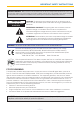
IMPORTANT SAFETY INSTRUCTIONS PRODUCT SAFETY: When used in the directed manner, this unit has been designed and manufactured to ensure your personal safety. Improper use of this product can result in potential electrical shock or fire hazards. Please read all safety and operating instructions carefully before installation and use, and keep these instructions handy for future reference. CAUTION RISK OF ELECTRIC SHOCK DO NOT OPEN CAUTION: To reduce the risk of electric shock do not remove cover (or back).
IMPORTANT SAFETY INSTRUCTIONS Recycling and Disposal Information: • Do not dispose of electronic devices or any of their components (especially batteries and LCD displays) in your municipal trash collection. • Consult your local waste management authority or a recycling organization like Earth911.com to find an electronics recycling facility in your area. CAUTION: Rechargeable batteries must be recycled or disposed of properly. WARNING: STRANGULATION HAZARD: Infants have STRANGLED in power cords.
IMPORTANT SAFETY INSTRUCTIONS CAUTION: Maintain electrical safety. Power line operated equipment or accessories connected to this product should bear the UL listing mark or CSA certification mark on the accessory itself and should not be modified so as to defeat the safety features. This will help avoid any potential hazard from electrical shock or fire. If in doubt, contact qualified service personnel. 9.
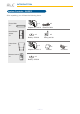
INTRODUCTION System Contents - AHS613 After unpacking, you will have the following items: Control Hub X 1 Door/Window Sensor X1 x1 Adaptor DC 12V/1A x1 x1 X1 Adaptor DC 5V/1 A Remote Control X1 Ethernet Cable x1 Battery CR2032 Indoor Siren x1 x1 Battery CR2032 —6— Sticky pad Set x1 Bracket x1 Screw Set
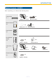
INTRODUCTION System Contents - AHS616 After unpacking, you will have the following items: Control Hub X 1 x1 Adaptor DC 12V/1A x1 Ethernet Cable Motion Detector X1 x3 x1 Battery AA 1.
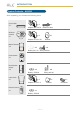
INTRODUCTION System Contents - AHS629 After unpacking, you will have the following items: Control Hub X 1 x1 Adaptor DC 12V/1A Wireless Camera X1 x1 Ethernet Cable x1 Adaptor DC 5V/1.5A x1 Bracket Motion Detector X2 x6 x2 Battery AA 1.
INTRODUCTION Getting to Know Your Security System The AHS616 is an upgradeable security system that comes with everything you need to start protecting your home. You can increase security at any time by adding additional sensors and/ or cameras. The system is easily accessed anywhere in the world via Internet. The free iOS/ Android App allows you to view/record video, turn power switch(es) on/off, activate/deactivate the siren manually or automatically.
GETTING STARTED Downloading the App u Download the ALC Connect App as follows: APPLE DEVICE: From your iPhone or iPad, go to the App Store and search for ALC Connect. ANDROID DEVICE: From your Android smartphone or tablet device, go to Google Play and search for ALC Connect. Pairing the Devices/Sensors The devices/sensors require sufficient battery power for successful pairing process and normal operation afterwards.
GETTING STARTED Pairing the Control Hub u Connect the supplied Ethernet cable from the router to the Ethernet jack on the back of the Control Hub. v Connect one end of the AC Adaptor to the DC IN jack on the rear of the Control Hub and the other end to a 120 volt AC (standard indoor) power outlet; the Red Power indicator will light and the unit will beep twice to indicate that the Control Hub is ready to set up. w Launch the previously installed ALC Connect App.
GETTING STARTED Pairing the Control Hub y The following screen will appear; enter the desired System name and the security code, if not in already. The default security code is 123456. U The newly added Control Hub is now added. NOTES: • If the Control Hub DID/Security Code cannot be retrieved, please check to make sure the Control Hub is powered on and the Ethernet cable is securely connected to the Wi-Fi router. • The Control Hub should be powered on and connected to the Wi-Fi router at all times.
GETTING STARTED Pairing the Camera Model AHS613 does not include a Camera. (Note: Any SightHD camera will work.) Connect the small end of the AC adaptor to the Camera’s DC IN jack. Plug the other end of the adaptor to a 120 volt AC (standard indoor) power outlet. After 30-60 seconds, the red Power Status LED will repeatedly blink three times rapidly. v Insert an SD Card (up to 32GB - not included) into the SD Card Slot. This will allow you to record videos. w At the Status screen, tap +. x Tap Camera.
GETTING STARTED Pairing the Camera y V Tap Next; the App will then search for the camera (this could take up to two minutes). If it does not detect, then manually enter the DID code located on the camera. U The following screen will appear; enter the desired Camera name, the Security Code and the Location. The default security code is 123456. Tap Save. — 14 — At the next screen, select the Camera. You may be asked to change the password and to select a Wi-Fi Network.
GETTING STARTED Pairing the Door/Window Sensor u The Door/Window Sensor comes with a pre-installed CR2032 battery. If it needs replacing, simply remove the cover by sliding it downwards and replace with a new CR2032 battery. v At the Status screen, tap +. w Tap Door/Window Sensor. x Tap Pair to start the Pairing process. Follow the on screen instructions.
GETTING STARTED Pairing the Door/Window Sensor y For initial setup, remove the insulating plastic tab; the App will then search for the sensor. If it does not detect, then manually see step 6. If detected, continue to step 7. U If it did not detect the sensor, pair manually by removing the battery cover and then reinstalling it (this will activate the manual pairing). The button for pairing is on the upper right of the battery.
GETTING STARTED Pairing the Motion Detector u The Motion Detector comes with three pre-installed AA batteries. If they need replacing, press the tab at the bottom of the sensor and insert three AA size batteries following the diagram in the compartment. v At the Status screen, tap +. x Tap Pair to start the Pairing process. Follow the on screen instructions. + + + w Tap Motion Detector.
GETTING STARTED Pairing the Motion Detector y For initial setup, remove the insulating plastic tab; the App will then search for the sensor. If it does not detect, see step 6; if detected, skip step 6 and continue with step 7. U If it did not detect the sensor, pair manually by removing the battery cover and then press the Pair button. V The following screen will appear; enter the desired Sensor’s name and the location. W Tap Save.
GETTING STARTED Pairing the Remote Control u The Remote Control comes with a pre-installed CR2032 battery. If it needs replacing, simply pull out the battery compartment on the side of the Remote Control and replace with a new CR2032 battery. v At the Status screen, tap +. w Tap Remote Control. x Tap Pair to start the Pairing process. Follow the on screen instructions.
GETTING STARTED Pairing the Remote Control y For initial setup, remove the insulating plastic tab; the App will then search for the Remote Control. If it does not detect, see step 6. If detected, continue to step 7. U If it did not detect the Remote Control, press and hold the Armed Stay button on the Remote Control until the blue LED blinks. V The following screen will appear; enter the desired Remote Control’s name and the location. W Tap Save.
GETTING STARTED Pairing the Indoor Siren u The indoor Siren can be operated via the AC Power supply or batteries. To use batteries, press the tab on the battery compartment cover and lift off. Insert four AA size batteries (not included) following the diagram in the compartment. v To use with AC, connect the small end of the AC adaptor to the Indoor Siren’s DC IN jack. Plug the other end of the adaptor to a 120 volt AC (standard indoor) power outlet. w At the Status screen, tap +. x Tap Siren.
GETTING STARTED Pairing the Indoor Siren y Tap Pair to start the Pairing process. Follow the on screen instructions. U The App will then search for the Indoor Siren. If the App did not detect the Siren, press the Pair button located inside the battery compartment in the back. V The following screen will appear; enter the desired Siren’s name and the location. W Tap Save.
GETTING STARTED Pairing the Power Switch Model AHS613 does not include an Power Switch. u At the Status screen, tap +. v Tap Power Plug. w Tap Pair to start the Pairing process. Follow the on screen instructions. x Plug the Power Switch into a standard AC outlet having 120V, 60Hz; the LED will blink indicating the Power Switch is in the pairing mode.
GETTING STARTED Pairing the Power Switch y If the Power Switch did not pair in step 3, manually pair by pressing and holding the AC button until the LED blinks blue. W Tap Save. U The following screen will appear; enter the desired Siren’s name and the location. REPEATER: The power switch can also be used as a ‘Repeater’. This function is for advanced users and allows certain devices to be used in further locations. For details, refer to Repeater section on page 45.
INSTALLATION Installation Tips The diagram below shows the suggested location(s) for the security system. Use this as a guide for your installation. The system is expandable with additional compatible wireless cameras, Motion Detectors, door/window contact sensors, sirens or other sensors (see pages 6-8 to see what is included with your kit) for greater protection. Control Hub Secure wireless central home control/management center. Remote Control Wireless multi-functional panic remote controller.
INSTALLATION Installation Tips WARNING: It is not recommended to use this camera outdoors. • Before you install the system, plan where and how it will be positioned, and where you will route the cable that connects the camera to the power adaptor(s). • Avoid having a direct light source in view of the camera. • Before starting permanent installation, have another person check the camera image on the tablet/phone when camera is positioned in the same place it will be permanently installed.
INSTALLATION Installing the Camera u If not mounting, but just using on a flat surface (desk, table, etc.), skip to step 2. Secure the multi-position Camera Bracket to a stable surface, ceiling or wall using the two screws. If needed, two anchors are also included. v Slide the camera into the Camera Bracket if mounting on ceiling or wall. Rotate the camera to the desired viewing angle. Note: See page 13, step 1 for connecting to AC Power.
INSTALLATION Installing the Door/Window Sensor Option B - Screws (included) u v Insert the first mounting screw directly onto the door/window frame (A). Hang the larger section on the mounted screw, remove the battery compartment cover and insert the second screw (B). Open the back cover of the small section. Use the two mounting screws to fix the back cover onto the movable part of the door/window frame (C - figure in step 1). Insert the sensor onto the back cover.
INSTALLATION Installing the Motion Detector Option B - Screws (Corner Bracket and Screws included) u v Flat Wall: Place the unit back onto the back cover. Corner: Hang on the corner bracket. Flat Wall: Remove back cover and insert the four screws as shown (A). Corner: Insert the two screws into the corner bracket as shown (B). Notes: • When it is finished, wave hand in front to see if App activates. • See page 17 for installing/replacing the batteries.
ALC CONNECT APP STATUS SCREEN Basic Operation u When first turning on the app you will enter the Control Hub Selection window. Simply tap your Control Hub to enter. v The Status screen will then appear; see below and the following pages for the details and operation of the Status page.
ALC CONNECT APP STATUS SCREEN Basic Operation Status Screen Icon Descriptions Door/Window Closed Door/Window Open Status Indicator ON Sensor On OFF Sensor Off Sensor Triggered Battery Low Tamper Alert Edit Icon (Appears in Edit Mode) w Delete Edit Mode Note: You will hear a beep and a pop-up window with a 30 second countdown appears. Tap Disarm if you accidentally tapped the wrong option, otherwise let the countdown finish. ARM AWAY and ARM STAY: Tap to Arm/Partially disarm the system.
ALC CONNECT APP STATUS SCREEN Basic Operation y Tap to enter the respective device’s Edit window, which will allow you to set the following: U Siren: Name and Location. You can also set the Siren volume. Door/Window Sensor: Name and Location. You can also set the Entry Delay Time to 30 seconds before the sensor activates. Remote Control: Name and Location. Power Switch: Name and Location. You can also set the Auto Off Time (when set with a scenario). Motion Detector: Name and Location.
ALC CONNECT APP STATUS SCREEN Basic Operation Set the following at the Camera’s Advanced Settings: Admin Password: Tap Modify to change the Admin Password. Time Zone: Tap to select the time zone you are in. Tap the checkbox to select daylight saving time. Device Security Code: Tap Modify to change the Device Security Code. Video Setting: Tap to set the Video Quality. Tapping Better Streaming will allow for faster video streaming, but the picture will not be as clear.
ALC CONNECT APP STATUS SCREEN Basic Operation Sensitivity Setting: Tap Detect Mode to set the desired Sensitivity Settings as follows: OFF: Turns sensitivity off. PIR: (Passive Infrared Sensor) is an electronic sensor that measures infrared (IR) light radiating from objects in its field of view. Software: Uses advanced software to achieve optimal motion sensitivity. SSID (Android): This is the network the camera is connected to.
ALC CONNECT APP STATUS SCREEN Device Control u On the Status window, tap a Device’s icon to turn the device on or off, or many various functions as described in this section. The Door/Window Sensor and Motion Detector do not have any control screens. v Siren: Tap the Siren icon, then turn the Siren On or Off. Tapping On will sound the Siren. w Remote Control: Tap the Remote Control icon and then an icon below to activate the respective function corresponding to the buttons on the remote control.
ALC CONNECT APP STATUS SCREEN Device Control Model AHS613 does not include a Camera. u On the Status window, tap the Camera. At this screen you can view the camera. v Tap the icons under the image to perform the following: Snapshot: Tap to capture screen images. The snapshots will be saved into the camera roll of your mobile device. Mute/Un-mute: Press to hear the sound of the camera’s microphone through the App. Tap again to mute the sound. Record: Tap to record. Video records for about two minutes.
ALC CONNECT APP SCENARIO SCREEN One-Touch Scenario Both the ‘One-Touch Scenario’ and the ‘Sequence Scenario’ are designed so you can customize the functions of the Remote Control buttons and the App controls (to mirror them) to setup items such as activate single/multiple cameras and sensors for recording and alerts, etc. This allows you to conveniently activate the security function(s) with a single touch when required.
ALC CONNECT APP SCENARIO SCREEN One-Touch Scenario u Tap the Scenario icon to enter the Scenario screen. v Tap w Tap one of the three one-touch scenarios you wish to edit. x You can now rename the one-touch scenario and check the desired device to activate upon pressing/ tapping; i.e. on ARM’s setup, you can set up the Camera for Arm Away or Arm Stay. Tap Save when done. — 38 — to enter the Edit mode.
ALC CONNECT APP SCENARIO SCREEN Sequence Scenario u Allows you to preset a sequence of events. For example, once the Motion Detector detects motion, the camera can begin recording and the light can turn on. Tap the Scenario icon to enter the Scenario screen. v Tap one of the Sequence Scenarios. w You will see a screen with “When...” followed by the main device. x Tap +. You will also see “Then...” which is where you will add items that will activate.
ALC CONNECT APP SCENARIO SCREEN Sequence Scenario y Select the desired device to activate by tapping it. Note that adding a device will automatically activate it. U Tap On or Off to set what status the selected device will be set to upon activation. Select Record or View if the Camera is added. Repeat steps 4 to 6 until the desired devices have been set. V To delete a device under “Then...”, tap to enter the Edit mode and then delete devices as desired. Tap Save when done.
ALC CONNECT APP EVENT SCREEN Operation u Tap the Event icon to enter the Event screen. v The list of triggered events will appear. If a video has been recorded, you can tap it to play it on the mobile device. Use the Play, Pause, Mute, and Unmute buttons during video playback. Notes: • Model AHS613 does not include a Camera. Video viewing is not available if there is no camera connected. • Video records for one minute when an alert has been triggered.
ALC CONNECT APP SETTING SCREEN Operation u Tap the Setting icon to enter the Setting screen. Enter the Admin Password (default is 123456). Tap Confirm when done. v The System Setting screen will appear. This section will describe the settings of this screen. w Tap IP Setup. If DHCP is selected, then the unit will automatically detect the Protocol settings. To manually set, uncheck and enter the options as per your IP. Tap Save when done. x Tap Security Setup.
ALC CONNECT APP SETTING SCREEN Operation y Tap Notification Setup. At this screen you can disable/enable Email Notifications and/or Push Notifications. Also set an email address to send alerts to. Tap Save when done. Notes: • Both Email and Push Notifications are available for System Arm, Disarm and/or trigger events generated from Camera, Motion Detector and Door/Window Sensor selected in the ARM/DISARM scenario section.
ALC CONNECT APP SETTING SCREEN Operation W Tap Firmware Update then tap Update to check for firmware updates. If one is available, tap Yes and install the new firmware. The App may restart. X Tap Remote Style. Tap to turn On or Off. If you turn on, next time you startup the app the screen will only display the Remote Control and Settings. To deactivate, go to Settings and tap Off in this option. at Tap System Alarm.
SETTING UP THE Power Switch AS A REPEATER Setup Model AHS613 does not include a Power Switch. u Make sure the Power Switch and the Sensor you want to “extend the range” have been successfully paired/ connected to the system Control Hub. v Press and hold the Power Switch button until the LED begins blinking blue and orange. While the LED is blinking blue and orange, activate the pairing mechanism on the End Sensor (pressing the Pairing button, removing the compartment, etc., see pages 23-24).
TROUBLESHOOTING If you have any trouble with your system, try these simple steps which should handle most common issues. Problem Control Hub Device not working. Possible Solution Make sure it is plugged into an AC Outlet and that the rear connection is inserted correctly. Make sure the Ethernet cable is connected to the rear of the Gatway and to a working router. A Sensor device is not working. Make sure fresh batteries are installed according to the diagram in the compartment.
TROUBLESHOOTING Factory Default/Reset Insert a paper clip or similar object into the Reset hole for five seconds and the system will start the reset process. The system will restore to factory default settings and you may start the Wi-Fi setup.
PRODUCT SPECIFICATIONS Control Hub Operation Voltage.................................................................................................... 12V DC/1A Ethenet.................................................................................................................10/100 Mbps Sub-1G....................................................................................................................916.8 MHz LED..................................................................................
PRODUCT SPECIFICATIONS Motion Detector Signal Frequency......................................................................................................916.8 MHz RF Range (open field conditions) ....................................................................................150 M Max. Detection Range.......................................................................................................16 M Detection Angle...............................................................................
WARRANTY One-Year Limited Warranty Important: Evidence of original purchase is required for warranty service. Atoms Labs LLC (“ALC”) ELEMENTS OF WARRANTY: ALC warrants, if properly installed and used thereafter in strict accordance with the use and care guidelines provided in the instructions manual, the Product shall be free from manufacturing defects in material and workmanship for one (1) year from the documented date of purchase.
ONE-YEAR LIMITED WARRANTY IMPORTANT: Evidence of original purchase is required for warranty service. WARRANTY WARRANTOR: Atoms Labs LLC (“ALC”) ELEMENTS OF WARRANTY: The ALC warranty covers the product for one (1) year from the documented date of purchase.
Wireless Made Simple. ALCWireless.com 061215_v1.
Wireless Made Simple. ALCWireless.