
User Manual

76/302 Issue 01 - April 2001 - Draft 04 3CC12424AAAA TQ BJA 01
76
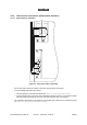
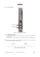
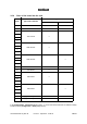
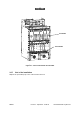
Figure 57 – Place of the boards into the DBS
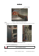
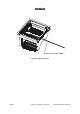
3.5.7 End of the installation
Replace the (removable) top cover of the rack and secure it.
ANT 1
ANT 2
TNT 1
TNT 2
TNT 3
TNT 4
AMD 1
AMD 2
AMD 3
AMD 4
CPL
IBS 1
IBS 2
IBS 3
IBS 4
PSU 1
PSU 2
V
HQW
1
2
7
3
4
6
5
109
8
13
11
14
12
15
17
16
19
18
20
25
23
2221
24
26
IBS 5
IBS 6
IBS 7
IBS 8
AMD 5
AMD 6
AMD 7
AMD 8
ID number
Slot number