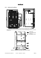
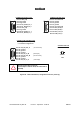
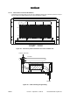
3.5.1 Mechanical installation X µ Figure 38 – Chassis dimensions and clearances (dimensions in mm) – Respect the requested clearances for the wiring, in order to avoid damage to the connectors (marked with an*).
– The installation of rack (optional) and chassis must enable the ventilation shown Figure 39 – Ventilation of the DBS chassis (cross-section). Do not obstruct the air inlets and outlets. Stages 1. Choose the location where the equipment is to be assembled and unpack the standard rack. If its top cover is fitted, remove it (quarter-turn screw). Note: place the rack in such a way that the cable connections are accessible before the rack is installed definitively. 2.
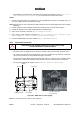
Stages (Figure 42 – DBS sub-rack power connection) 1. Connect the switch at the top of the DBS sub-rack to the external DC power source. You are recommended to pass the power supply cable via the top of the rack. ATTENTION: DO NOT CONNECT THE GROUNDING CABLE TO THE SWITCH BUT TO THE YELLOW/GREEN TERMINAL BLOCK. 2. Ground the DBS sub-rack. Note: a ground strip is fixed to the backplane and ensures its grounding.
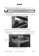
3.5.3 Customer access connections (circuits interfaces) Considerations This connection involves the use of: – either direct connectors TNT1 to TNT4, (corresponding to TNT board plug into the chassis) at the top of the DBS sub-rack, if no distribution frames (cf. § 3.5.3.1 Direct connections to the connectors of the top panel of the DBS chassis.
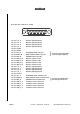
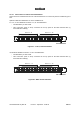
CONNECTOR TEST#1 J101 CONNECTOR NMS J102 Pin 01: SDA_Fdp Pin 02: ground Pin 03: ground Pin 04: PC_RS232_Rx_1 Pin 05: PC_RS232_Rx_0 Pin 06: SCL_Fdp Pin 07: ground Pin 08: PC_RS232_Tx_1 Pin 09: PC_RS232_Tx_0 Pin 01: not connected Pin 02: ground Pin 03: ground Pin 04: ground Pin 05: not connected Pin 06: 10BT_RxD_M Pin 07: 10BT_RxD_P Pin 08: 10BT_TxD_M Pin 09: 10BT_TxD_P CONNECTOR SYNCHRO J103 Clock signals have no polarity ––> P and M not significant CONNECTOR J113 Pin 01
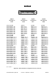
C o n n e c to r A la r m s J 1 0 4 Pin 01: I_AL_0 Pin 02: I_AL_2 Pin 03: I_AL_4 Pin 04: I_AL_6 Pin 05: ground Pin 06: ground Pin 07: ATT_B Pin 08: NURG_B Pin 09: URG_B Pin 10: CMD_4_B Pin 11: CMD_3_B Pin 12: CMD_2_B Pin 13: CMD_1_B Pin 14: I_AL_1 Pin 15: I_AL_3 Pin 16: I_AL_5 Pin 17: I_AL_7 Pin 18: Ground Pin 19: ATT_A Pin 20: NURG_A Pin 21: URG_A Pin 22: CMD_4_A Pin 23: CMD_3_A Pin 24: CMD_2_A Pin 25: CMD_1_A 66/302 76 Remote signaling input 1 Remote signaling input 3 Remote signaling inp
TNT#1 E1/T1#1–8 J105 Pin 01: ground Pin 02: Input_1_P_1 Pin 03: Input_2_P_1 Pin 04: Input_3_P_1 Pin 05: Input_4_P_1 Pin 06: Input_5_P_1 Pin 07: Input_6_P_1 Pin 08: Input_7_P_1 Pin 09: Input_8_P_1 Pin 10: ground Pin 11: ground Pin 12: Output_1_P_1 Pin 13: Output_2_P_1 Pin 14: Output_3_P_1 Pin 15: Output_4_P_1 Pin 16: Output_5_P_1 Pin 17: Output_6_P_1 Pin 18: Output_7_P_1 Pin 19: Output_8_P_1 Pin 20: ground Pin 21: Input_1_M_1 Pin 22: Input_2_M_1 Pin 23: Input_3_M_1 Pin 24: Input_4_M_1 Pin 25: Input_5_
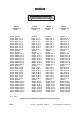
TNT#3 E1/T1#1–8 J109 Pin 01: ground Pin 02: Input_1_P_5 Pin 03: Input_2_P_5 Pin 04: Input_3_P_5 Pin 05: Input_4_P_5 Pin 06: Input_5_P_5 Pin 07: Input_6_P_5 Pin 08: Input_7_P_5 Pin 09: Input_8_P_5 Pin 10: ground Pin 11: ground Pin 12: Output_1_P_5 Pin 13: Output_2_P_5 Pin 14: Output_3_P_5 Pin 15: Output_4_P_5 Pin 16: Output_5_P_5 Pin 17: Output_6_P_5 Pin 18: Output_7_P_5 Pin 19: Output_8_P_5 Pin 20: ground Pin 21: Input_1_M_5 Pin 22: Input_2_M_5 Pin 23: Input_3_M_5 Pin 24: Input_4_M_5 Pin 25:
3.5.3.2 Connections to 75 ohm coaxial distributors Connections are made beneath the roof of the standard rack or on the front panel for a different type of rack. Optional cables and distributors are in the installation set. 1.6 / 5.6, 75 ohm distributor for16 E1 / T1, ref: 3CC08061Axxx. – One distributor per TNT board. – TNT connectors (J105 to J112) connected to the top panel of the DBS subrack with (n) 3CC11236Axxx cable(s).
3.5.3.3 Connections to 120 ohm distributors – Connections to 120 ohm (E1) or 100 ohm (T1) distributor of the TNT connectors (J105 to J112) of the top panel of the DBS subrack with (n) 3CC11238Axxx cable(s).