
User Manual

62/302 Issue 01 - April 2001 - Draft 04 3CC12424AAAA TQ BJA 01
76
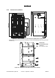
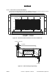
– The installation of rack (optional) and chassis must enable the ventilation shown Figure 39 – Ven-
tilation of the DBS chassis (cross-section). Do not obstruct the air inlets and outlets.
Stages
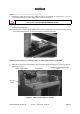
1. Choose the location where the equipment is to be assembled and unpack the standard rack. If its
top cover is fitted, remove it (quarter-turn screw).
Note: place the rack in such a way that the cable connections are accessible before the rack is installed
definitively.
2. Unpack the DBS chassis assembly and install it inside the rack. Fix and screw into place.
3. Unpack the DC/DC PSUs; install and plug them in the DBS chassis.
4. Carry out the electrical connection, cf. § 3.5.2 Electrical connection.
5. Carry out the client terminal connections, cf. § 3.5.3 Customer access connections (circuits
interfaces) and 3.5.4 Client access connections (ATM network interface).
6. Connect the RBS/DBS connection cable(s) cf. § 3.5.5 RBS/DBS Connection.
3.5.2 Electrical connection
Considerations
– The DBS chassis is supplied from the rated DC voltage of 48V (minimum 35V, maximum 60V).
– The cable connecting the external DC power source to the DBS sub-rack will have a minimum
cross-section of 3x10 mm
2
and a maximum length of 20 meters.
– The rack must be grounded to the general grounding system. For this, the rack mechanism will be
connected by a cable with a minimum cross-section of 16 mm
2
, attached using a 6 mm bolt.
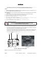
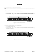
– For the power supply block diagram, refer to Figure 40 – DBS chassis power supply:
Figure 40 – DBS chassis power supply
Note: The user must connect +48V or -48V to ground.
WHEN MAKING THE POWER CONNECTIONS, TURN OFF ALL DBS
CHASSIS EXTERNAL POWER SOURCES.
0V/+48V
–48V/0V
Grounding
Fuse holder
ON – OFF switch
Fuse cartridge GRC
14x51 40 Amp.