
User Manual

3CC12424AAAA TQ BJA 01 Issue 01 - April 2001 - Draft 04 63/302
76
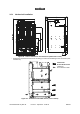
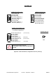
Stages (Figure 42 – DBS sub-rack power connection)
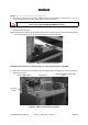
1. Connect the switch at the top of the DBS sub-rack to the external DC power source. You are
recommended to pass the power supply cable via the top of the rack.
2. Ground the DBS sub-rack.
Note: a ground strip is fixed to the backplane and ensures its grounding. The rack and subrack ground
are screwed together, thus no special grounding is required for the rack.
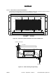
Figure 41 – DBS sub-rack ground connection
Earthing must be done very carefully in order to assure good operation of the DBS.
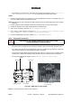
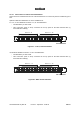
3. Make sure that the fuses are inserted in the fuse-holder. Before changing fuse, make sure that the
switch is set to OFF.
Figure 42 – DBS sub-rack power connection
ATTENTION: DO NOT CONNECT THE GROUNDING CABLE TO THE SWITCH
BUT TO THE YELLOW/GREEN TERMINAL BLOCK.
Fuse-holderPower supply cables
ON - OFF
Switch
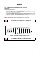
Winding cassette for fiber optic
cables