
User Manual

64/302 Issue 01 - April 2001 - Draft 04 3CC12424AAAA TQ BJA 01
76
3.5.3 Customer access connections (circuits interfaces)
Considerations
This connection involves the use of:
– either direct connectors TNT1 to TNT4, (corresponding to TNT board plug into the chassis) at
the top of the DBS sub-rack, if no distribution frames (cf. § 3.5.3.1 Direct connections to the con-
nectors of the top panel of the DBS chassis.);
– or the optional distribution frames at the top of the DBS sub-rack in the standard rack (coaxial
cables for the 75 ohm links, balanced pair cables for the 120 ohm links cf. § 3.5.3.2 Connections
to 75 ohm coaxial distributors and § 3.5.3.3 Connections to 120 ohm distributors).
Note: the provided equipment is already connected and parts of the installation kit.
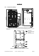
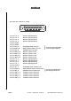
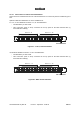
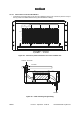
3.5.3.1 Direct connections to the connectors of the top panel of the DBS chassis.
Note: All connectors are female connectors.
Figure 43 – Top panel DBS connections: connectors location
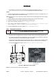
ALL CUSTOMER ACCESS CABLES MUST BE SHIELDED TYPE.
DO NOT REMOVE THE COVER ON CONNECTOR TEST J113.
TEST#1
NMS
(10baseT)
SYNCHRO
2,048Mz
ALARMS
I/O
TNT#1
E1/T1#1–8
TNT#1
E1/T1#9–16
TNT#2
E1/T1#1–8
TNT#2
E1/T1#9–16
TNT#3
E1/T1#1–8
TNT#3
E1/T1#9–16
TNT#4
E1/T1#1–8
TNT#4
E1/T1#9–16
TEST#2
J101
J102
J104
J103
J105 J106 J107 J108 J109 J110 J111 J112
J113