
User's Manual


64/70 Issue 01 - April 2001 - Draft 03 3CC12425AAAA TQ BJA 01
66
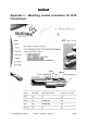
Figure 31 – Exposing the shield and center conductor
5. Pull the braided shielding back over the jacket and inspect the exposed end. Ensure that it is clean
(free of loose pieces of shielding).
6. Attach the Stirling connector.
• To attach an SPP-6-0 or SPP-59-0 connector, carefully insert the cable into the connector until
you feel the cable click into place. Do not try to remove the connector after it has been put on
the cable.
• To attach an SPP-11-newbridge connector:
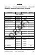
• Position the dielectric at the base of the stripper/activator tool and measure the length of
the center conductor against the first mark on the activator. Figure 33 identifies the activator
base and markings. If necessary, trim the conductor with circular wire cutters.
Figure 32 – Measuring the center conductor
Caution - A poor connection may result if the connector is removed from
the cable once it has clicked into place
First
line
Base of
activator