
User's Manual


3CC12425AAAA TQ BJA 01 Issue 01 - April 2001 - Draft 03 65/70
66
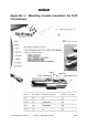
• Position the center conductor at the second line on the stripper/activator tool and mark the
cable jacket with your thumbnail at the base of the activator; see Figure 33.
Figure 33 – Measuring and marking the 5916 cable
• Carefully place the connector on the cable and push the connector until it meets the thum-
bnail mark. If the connector is pushed too far onto the cable, it may not properly connect to
its mate connector.
7. Remove the connector cap and insert the connector into the activator tool (the center conductor fits
into the hole in the crank). Turn the handle to tighten the activator until it stops, then back off the
activator and remove the connector; see Figure 34.
Figure 34 – Fitting the connector
8. Check the installation by pulling on the connector. The connector should not come off.
If the connector is not being connected immediately, put the cap back on it.
Caution - A poor connection may result if the connector is removed from the cable
once it has been pushed onto the cable.
Second
line
Mark
jackethere
Crank
Connector