
User's Manual


90/346 Issue 01 - April 2001 - Draft 04 3CC12426AAAA TQ BJA 01
104
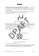
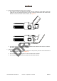
Figure 69 – Removing the cable jacket
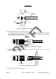
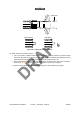
2. Install the O-ring on the first corrugation valley as shown in Figure 70.
Figure 70 – Installing the small O-ring
3. Use the small brush to lubricate the O-ring with the silicone grease included with the connector.
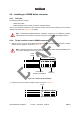
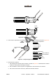
4. Install the connector body on the cable by sliding it over the cable end until it is stopped by the O-
ring, as shown in Figure 71. Install the spring ring on the first corrugation valley after the cable body,
as shown in Figure 71.
Figure 71 – Installing the connector body and spring ring
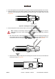
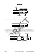
5. Slip the outer conductor cutting guide over the cable and onto the spring ring, as shown in Figure 72.
51 mm (2 in.) or greater
Outer
conductor
Lowest point
between corrugations
Cable
jacket
O-ring
Connector body
Spring ring