
User's Manual


82/346 Issue 01 - April 2001 - Draft 04 3CC12426AAAA TQ BJA 01
104
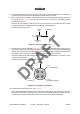
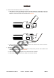
Figure 53 – .Putting the insert into the insert carrier
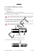
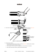
13. Put the insert carrier into the connector body; see Figure 54.
The red dot on the outer shell aligns with the tab on the insert carrier. You should feel a slight click
when the carrier locks into place. It may be necessary to gently push the cable while carefully rotating
the connector body until the click is felt.
Figure 54 – Inserting the insert carrier into the outer shell
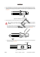
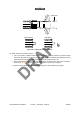
14. Tighten the connector by turning the collet nut to 6.9 Nm (5 ft-lb) of torque; see Figure 55. Do not
rotate the connector body.
Figure 55 – Tightening the connector
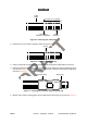
15. Push the bend relief on to the collet nut.
Insert
carrier
Bevel
Cutout in carrier
Pins
Tab on
insert
Tab on
carrier
Insert
Tab on insert carrier
Red dot
Do not turn