
User's Manual


84/346 Issue 01 - April 2001 - Draft 04 3CC12426AAAA TQ BJA 01
104
3. Use a small grease brush to lubricate the O-ring with the silicone grease shipped with the connector.
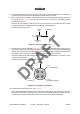
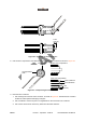
4. Install the clamping nut on the cable by sliding it over the cable end until it is stopped by the O-ring.
The fingers of the clamping nut should stop exactly half-way through a corrugation peak, as shown
in Figure 58.
Figure 58 – Installing the clamping nut
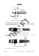
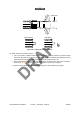
5. Remove the portion of outer conductor that is not covered by the clamping nut.
1. Use a fine-tooth saw to cut through the outer conductor flush with the clamping nut fingers. Do
not cut deeper than the outer conductor, and make sure that the cut is made along the entire
circumference where the clamping nut fingers meet the outer conductor; see Figure 59.
Figure 59 – Cutting the outer conductor
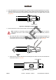
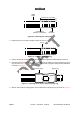
2. Grasp the outer conductor with pliers, and carefully pull it off. When removed, the foam dielectric
is exposed, as seen in Figure 60.
Figure 60 – Foam dielectric
Note - Substep i is unnecessary if Heliax cable tool 207886 was used in step 1 to score the
cable jacket, and cut the outer conductor. If the Heliax cable tool was used, proceed to
substep 2.
Clamping nut
Foam dielectric