
User's Manual


88/346 Issue 01 - April 2001 - Draft 04 3CC12426AAAA TQ BJA 01
104
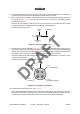
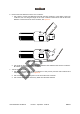
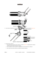
Figure 65 – Soldering the pin
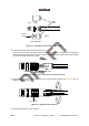
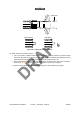
11. Verify that the pin is installed at a 90° angle with respect to the clamping nut, as shown in Figure 66.
If the pin is not straight, and cannot be corrected, remove it, and start the procedure again.
Figure 66 – Checking the pin
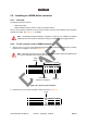
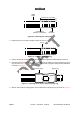
12. Add the large O-ring to the clamping nut, as shown in Figure 67.
Pin cup
Deburred inner
conductor
Solder
hole
Solder
bead
Soldering
pliers
Heat
shield
90°