
User's Manual
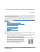

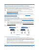
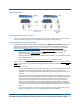
Table Of Contents
- Internal-Antenna OmniAccess AP Quick Installation Guide

3/16/04 Step 2: Configuring the OmniAccess AP Before Installation
90-100831-000 Rev 5Alcatel OmniAccess Wireless Access Point Quick Installation Guide 9
- Make sure that a DHCP server is configured in the Alcatel OmniAccess Switch or
Appliance for both the Management Interface and AP-Manager Interface using the CLI,
Web Browser, or ACS interface, and that the DHCP server is operating correctly.
- Once the AP finds the Alcatel OmniAccess Switch or Appliance, it attempts to download
the new Alcatel Wireless Operating System code if the AP code version differs from the
Alcatel OmniAccess Switch or Appliance code version. While this is happening, the LEDs
on the top of the AP blink on and off together.
4. Once the Alcatel Wireless Operating System code download is successful, the AP reboots. The
GREEN LED turns on and the two YELLOW/AMBER/ORANGE LEDs indicate the states of the
802.11a and 802.11b/g networks. If any part of the network is disabled in the Alcatel Omni-
Access Switch or Appliance, the corresponding YELLOW/AMBER/ORANGE LED remains off.
- Note that the Red LED can light for a short period (10-20 seconds) when the AP
reboots. If the RED LED comes on AND STAYS ON for more than a minute, disconnect
the AP and call Alcatel Technical Support.
- From the CLI, Web Browser or ACS interface, configure the AP with its Primary Alcatel
OmniAccess Switch or Appliance name as described in the Alcatel OmniAccess Wireless
Product Guide.
- If required, use the CLI, Web Browser or ACS interface to customize the AP-specific
802.11a, 802.11b and 802.11g network settings. Once again, the two YELLOW/AMBER/
ORANGE LEDs indicate the states of the 802.11a and 802.11b/g networks. If any part
of the network is disabled, the corresponding YELLOW/AMBER/ORANGE LED remains
off.
5. If everything works (the GREEN LED is on and the RED LED is off), disconnect the AP and take
it to its final destination and install it as described in this document. If your OmniAccess AP fails
this visual test, refer to RMA Procedures in the Alcatel OmniAccess Wireless Product Guide to
return your OmniAccess APs.
Note: When you are installing a Layer 3 OmniAccess AP on a different subnet than the Alcatel
OmniAccess Switch or Appliance, MAKE SURE that a DHCP server is available on the subnet
where you will be installing the AP, and that the subnet has a route back to the Alcatel Omni-
Access Switch or Appliance. Also make sure that the route back to the Alcatel OmniAccess
Wireless Switch or Appliance has destination UDP ports 12222 and 12223 open for LWAPP
communications. Ensure the route back to the Primary Alcatel OmniAccess Switch or
Appliance allows IP packet fragments. Finally, make sure that if address translation is used,
that the AP and the Alcatel OmniAccess Switch or Appliance have a static 1-to-1 NAT to an
outside address. (Port Address Translation is not supported.)
6. When you have installed and powered up the AP in its final destination, verify that the LEDs are
in the same state they were in at the end of Step 4. If no LEDs are on, the AP is most likely not
receiving power. If the LEDs all the LEDs blink sequentially back and forth for more than five
minutes, the AP is unable to find its Primary Alcatel OmniAccess Switch or Appliance. Check the
connection between the AP and the Alcatel OmniAccess Switch or Appliance, and make sure the
AP and the Alcatel OmniAccess Switch or Appliance are either on the same subnet or that the
AP has a route back to its Primary Alcatel OmniAccess Switch or Appliance. Also, if the Omni-
Access AP is not on the same subnet as the Alcatel OmniAccess Switch or Appliance, make sure
there is a DHCP server on the same subnet as the OmniAccess AP.
After you have prepared all OmniAccess APs, reconfigure the Alcatel OmniAccess Switch or Appliance so
it is not the Master. A Master Alcatel OmniAccess Switch or Appliance should only be used for config-
uring OmniAccess APs and not in a working network.
After completing Step 2: Configuring the OmniAccess AP Before Installation
for all OmniAccess APs and
OmniAccess 1200R APs, continue with Step 3: Preparing Mounting Locations
.