
User's Manual

Cable connections in the Modular Cell 4.0B cabinets
3- 33
Lucent Technologies – Proprietary
See notice on first page
401-703-454
FOA Draft Issue 1
January, 2006
............................................................................................................................................................................................................................................................
Prepare the T1/E1 and user
alarm cables for
punchdown and ground
connection at the facilities
interface module
Prepare the T1/E1 and user alarm cables for punchdown at the EFIM
(facilities interface module). User alarm cables are attached only at the
primary cabinet.
................................................................................................................................
............................................
1 Allow adequate slack and cut the T1/E1 and user alarm cable to the
correct length.
................................................................................................................................
............................................
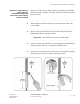
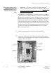
2 Strip the outer cable insulation to expose 200 mm (8 inches) of the
braided shield. Refer to the figure below.
Important! Be careful not to cut into the cable shield.
................................................................................................................................
............................................
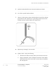
3 At the end of the outer insulation, cut an opening in the braided shield,
and the insulation inside it, to expose the individual wires.
................................................................................................................................
............................................
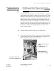
4 Using a hook or equivalent tool, pull the wires out through the opening
made in the previous step, as shown in the figure below.