
User's Manual

3-36
Lucent Technologies – Proprietary
See notice on first page
401-703-454
FOA Draft Issue 1
January, 2006
...........................................................................................................................................................................................................................................................
Cable connections in the Modular Cell 4.0B cabinets
Punch down T1/E1 lines on
the EFIM in Modular Cell
4.0B cabinets that accept a
maximum of twelve T1/E1
lines
Important! If installing a Modular Cell 4.0B cabinet that
accepts a maximum of twenty T1/E1 lines, skip to Punch down T1/
E1 lines on the EFIM in Modular Cell 4.0B cabinets that accept a
maximum of twenty T1/E1 lines on Page 3 - 41 and continue the
installation from that point.
Some Modular Cell 4.0B primary or dual band cabinets are equipped
with USRs (Universal Radio Controllers) as opposed to UCRlls. These
Modular Cell 4.0B cabinets accepts a maximum of twelve T1/E1 lines.
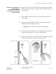
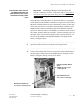
The T1/E1 lines will be connected to the punchdown terminals on the
EFIM (facilities interface module) inside of the Modular Cell 4.0B
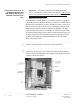
primary or dual band cabinet. The EFIM is accessible from the front of
the cabinet, behind a slide-out tray (EFIT - facilities interface tray). See
the figure below. Use the following procedure to punch down the T1/
E1 lines on the EFIM in the applicable Modular Cell 4.0B cabinet.
Refer to the figure below.
................................................................................................................................
............................................
1 Open the facilities interface tray. Refer to the figure below.
................................................................................................................................
............................................
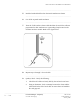
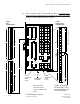
2 Connect the twisted ends of the T1/E1 cable shield to the grounding
clamp located on the EFIM. Refer to the figure below. Refer to the figure
on Page 3-38 for more detail.
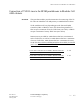
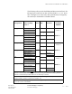
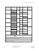
* FOR PROTECTOR LOCATIONS OF ADDITIONAL T1/E LINES,
REFER TO THE FIGURE AND TABLES THAT FOLLOW