
User's Manual

Cable connections in the Modular Cell 4.0B cabinets
3- 37
Lucent Technologies – Proprietary
See notice on first page
401-703-454
FOA Draft Issue 1
January, 2006
............................................................................................................................................................................................................................................................
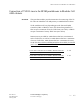
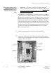
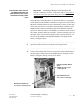
Important! Before performing the next step, consult the
customer / site engineer for the site preparation data sheet that is
provided in the Flexent
Modular Cell 4.0/4.0B Outdoor Site
Preparation Guidelines, 401-703-413. The site preparation data
sheet is provided to allow the customer a means to record the T1/
E1 line assignments for punchdown at the EFIM, and to convey
that information to the installer. The data should include the TX/
RX signal pair assignments and their color codes for each line
number to be attached. Note that the T1/E1 line numbers do not
correspond to the silk-screened TX/RX signal pair labels on the
EFIM. Also note that the TX and RX punchdowns TX1/RX1
through TX12/RX12,are not located in numerically consecutive
order.
................................................................................................................................
............................................
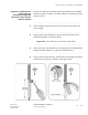
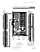
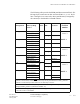
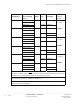
3 Connect the T1/E1 wire pairs as follows. Refer to the figure on Page 3-
38, Note 1, and the table on Page 3 - 39.
• Connect the applicable T1/E1 wire pairs to connector J1 and J2
punchdowns, signals TX1/RX1 through TX12/RX12, as assigned
by the customer on the site preparation data sheet.
................................................................................................................................
............................................
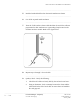
4 Check that two surge protectors are installed in the correct protector
locations for each installed line. Refer to the figure on Page 3-38, and
the table on Page 3 - 39.
................................................................................................................................
............................................
5 Close and secure the EFIT with the four screws.