
User's Manual

5-72
Lucent Technologies – Proprietary
See notice on first page
401-703-454
FOA Draft Issue 1
January, 2006
...........................................................................................................................................................................................................................................................
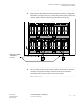
Component installation in the Modular Cell 4.0B and the
WNG24-BC battery cabinets
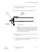
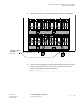
Place the battery negative
and positive bus bars
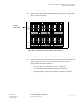
Refer to the figure on Page 5-77, and perform the following steps to
connect the negative and positive bus bars.
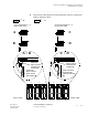
Important! Although all four parallel bus bars are identical,
observe that the orientation of the positive and negative parallel
bus bars is different on the left three batteries (1, 2 and 3) than on
the right three batteries (4, 5 and 6). Also observe that the negative
and positive pairs are positioned in a reverse orientation to each
other. Refer to the figure on Page 5-77.
................................................................................................................................
............................................
1 Apply antioxidant compound to the positive (+) terminal and
negative (-) terminal of all batteries.
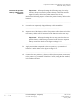
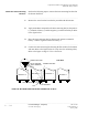
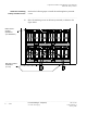
Important! When performing the next two steps, refer to the
Step 5 figure on Page 5- 73. For batteries 1, 2, and 3, use "A" for
positive bus bar installation and "B" for negative bus bar
installation. For batteries 4, 5, and 6, use "C" for negative bus bar
installation and "D" for positive bus bar installation.
................................................................................................................................
............................................
2 Place bus bars on batteries 1, 2, and 3.
• Place a bus bar (A) on the positive terminals with the bend facing
toward the batteries.
• Place a bus bar (B) on the negative terminals with the bend facing
away from the batteries.
................................................................................................................................
............................................
3 Place bus bars on batteries 4, 5, and 6.
• Place a bus bar (C) on the negative terminals with the bend facing
toward the batteries.
• Place a bus bar (D) on the positive
terminals with the bend facing
away from the batteries.
................................................................................................................................
............................................
4 Temporarily secure each bus bar in place with a washer and nut.