
User's Manual
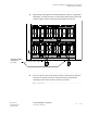

Component installation in the Modular Cell 4.0B and the
WNG24-BC battery cabinets
5- 77
Lucent Technologies – Proprietary
See notice on first page
401-703-454
FOA Draft Issue 1
January, 2006
............................................................................................................................................................................................................................................................
................................................................................................................................
............................................
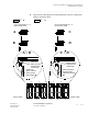
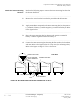
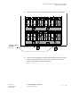
5 Repeat steps 1 through 4 for the remaining battery shelves, if applicable.
Refer to the figure below.
................................................................................................................................
............................................
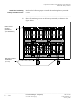
6 Torque the following connections using an insulated 10-mm socket and
torque wrench set at 62 in.-lb. (7.0 Nm). Do not use the torque
specifications provided in Chapter 1.
• All series bus bar connections (+ and -, all shelves)
• All remaining positive battery connections, all shelves
• Negative battery connections on batteries 5 and 6, all shelves
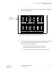
S-2
1
2
3
4
5
6
1
2
3
4
5
6
S1
S2
SERIES
BUS BARS
S-1
BATTERY CABLES NOT SHOWN FOR CLARITY