
User's Manual


Modular Cell 4.0B and WNG24-BC cabinet handling,
placement, anchoring and grounding
2- 9
Lucent Technologies – Proprietary
See notice on first page
401-703-454
FOA Draft Issue 1
January, 2006
............................................................................................................................................................................................................................................................
Set the 12-mm expansion
stud anchors for mounting
bases
Important! If using “12-mm expansion stud anchors” without
mounting bases, skip to Cabinet handling on Page 2 - 21 and
continue the installation from that point.
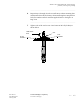
Perform the following steps to install the 12-mm expansion stud
anchors for mounting bases. Refer to the figure on Page 2-10. Note that
the black shouldered spacer and red cap, included in each zone 3 and 4
anchor kit, are not used.
Important! When performing the next step, use a 1/4-inch
socket to protect the head of the threaded rod if it is necessary to
tap the anchor assembly into place. Note that the black shouldered
spacer and red cap, included in each zone 3 and 4 anchor kit, are
not used.
Important! If a 4-inch hole depth was not attained for the
anchor, the removable spacer may be removed from the anchor
assembly and 1 inch may be cut from the end of the threaded rod.
................................................................................................................................
............................................
1 Remove the tape and insert the anchor assembly into the hole until the
large washer is flat against the surface. Refer to the figure on Page 2-10,
Item A.
................................................................................................................................
............................................
2 Tighten the top nut with a torque wrench to 50 ft-lb (68 Nm). This sets
the anchor, as shown in the figure, Item B.
................................................................................................................................
............................................
3 Loosen the nut, as shown in the figure, Item C1.
................................................................................................................................
............................................
4 Remove the threaded rod and nut assembly (with washers) using the
1/4-inch drive at the top, as shown in the figure, Item C2. The set anchor
remains in the anchor hole, as shown in the figure, Item D.
................................................................................................................................
............................................
5 Tape over the open anchor to prevent debris from falling into the hole.