
User's Manual


Modular Cell 4.0B and WNG24-BC cabinet handling,
placement, anchoring and grounding
2- 49
Lucent Technologies – Proprietary
See notice on first page
401-703-454
FOA Draft Issue 1
January, 2006
............................................................................................................................................................................................................................................................
................................................................................................................................
............................................
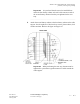
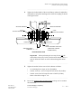
4 Tighten the locknut inside of the second battery cabinet (if applicable),
and install a 2-inch plastic bushing on the end of the coupling, as shown
in the figure below.
Important! When performing the next step, do not seal the
anchor holes in any way. In the event that water should collect, it
must be allowed to drain out of the cabinet through the anchor
holes.
................................................................................................................................
............................................
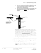
5 Tighten the anchor bolts or nuts on both cabinets as follows.
• On mounting bases: torque to 50 ft-lb (68 Nm)
• Seismic zones 0, 1, and 2: Torque the bolts to 18 ft-lb (24 Nm).
• Seismic zones 3 and 4: Torque the nuts to 58 ft-lb (79 Nm).
Refer to the table on Page 2 - 29.
................................................................................................................................
............................................
6 Proceed to Install the cabinet grounding cables on Page 2-65 to continue
the installation.
BOTTOM FRONT VIEW
2-inch
PLASTIC BUSHING
SEALING WASHER*
AREA BETWEEN
CABINETS
LOCK NUT
2-inch
FEED-THROUGH COUPLING
2-inch
P
LASTIC BUSHING
SEALING WASHER*
LOCK NUT
FIRST WNG24-BC
BATTERY CABINET
SECOND WNG24-BC
BATTERY CABINET
*(”BOX SIDE” FACING
CABINET WALL)