
User's Manual


Finishing the installation
7- 15
Lucent Technologies – Proprietary
See notice on first page
401-703-454
FOA Draft Issue 1
January, 2006
............................................................................................................................................................................................................................................................
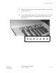
Connect RF antenna
jumper cables to the
antenna cables
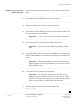
Use the following procedure to terminate and connect the RF antenna
jumper cables to the applicable antenna cables.
................................................................................................................................
............................................
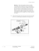
1 Route the RF antenna jumper cables from the Modular Cell 4.0B
primary or 4.0B dual band cabinet to the RF antenna connections.
................................................................................................................................
............................................
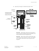
2 Connect the RF antenna cable to the applicable RF antenna connection
at the surge suppressor.
Important! For a profile view of the sound muffler, refer to
Chapter 1,
Modular Cell 4.0B cabinet side view 1 on Page 1 - 26. For
alternate cable routings refer to Chapter 1, Modular Cell 4.0B cabinet
side view 2 on Page 1 - 27.
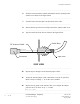
MODULAR CELL
CABINET
RUBBER
BOOT (LUCENT
PROVIDED)
DRIP LOOP
ANTENNA JUMPER
CABLE SUPPORT STRUCTURE
ICE BRIDGE
(IF REQUIRED)
WATER PROOFING
(OPTIONAL)
4-FOOT COAXIAL ANTENNA
JUMPER CABLES (1/2 - INCH
)
(LUCENT SUPPLIED)
ANTENNA & GPS
CABLES
#6AWG STRANDED INSULATED
GROUND WIRE TO MAIN GROUND BUS
MAIN GROUND BUS
(2) #2 AWG BARE
SOLID TINNED COPPER
WIRE TO GROUND ELECTROD
E
SYSTEM
FINISHED GRADE
RF & GPS
SURGE PROTECTORS
CONCRETE PAD
REAR HEAT
EXCHANGER
(If applicable)
THESE PARTS NOT PRESENT ON
DUAL BAND CABINETS