Alcatel-Lucent 8950 AAA (Authorization, Authentication, Accounting) User’s Guide | Release 6.0 365-360-001R6.
Alcatel, Lucent, Alcatel-Lucent and the Alcatel-Lucent logo are trademarks of Alcatel-Lucent. All other trademarks are the property of their respective owners.. The information presented is subject to change without notice. Alcatel-Lucent assumes no responsibility for inaccuracies contained herein. Copyright © 2008 Alcatel-Lucent. All Rights Reserved.
Contents About this information product Where to go First ....................................................................................................................................... 1-ii How This Manual Is Organized ...............................................................................................................1-iii Conventions ..............................................................................................................................................
Contents ............................................................................................................................................................................................................................................................ The Diameter Peers tab ............................................................................................................................. 5-8 The TACACS+ Clients tab ........................................................................
Contents ............................................................................................................................................................................................................................................................ Adding an Access Rule ......................................................................................................................... 11-13 Modifying a System Operator .......................................................................
Contents ............................................................................................................................................................................................................................................................ General Info ............................................................................................................................................ 18-3 License Information ......................................................................
Contents ............................................................................................................................................................................................................................................................ Part VI: Database Tools Navigation Pane 23 Creating and Managing User Profiles with the Built-in Database Understanding Database Users ................................................................................................................
Contents ............................................................................................................................................................................................................................................................ .........................................................................................................................................................................................................................................................
About this information product Overview Purpose Welcome, you are about to embark on a course to set up secure access to your network with the industry’s leading RADIUS server, 8950 AAA. It provides you the highest level of control and management of a wide range of access services. These services range from simple dial-up remote access using Point-to-Point Protocol (PPP), Local Area Network (LAN) access, wireless (Wi-Fi) and wired, and even access to core network elements such as switches and routers.
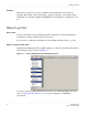
Where to go First ............................................................................................................................................................................................................................................................ Audience This guide is designed to be used by qualified system administrators and network managers. Knowledge of basic networking concepts is required to successfully install 8950 AAA.
How This Manual Is Organized ............................................................................................................................................................................................................................................................
How This Manual Is Organized ............................................................................................................................................................................................................................................................ Chapter 6, “Configuring 8950 AAA Realm Routing Table Properties” This chapter discusses the process of configuring the Realm Routing Table.
How This Manual Is Organized ............................................................................................................................................................................................................................................................ Chapter 16, “Message Logging” This chapter discusses how to determine the information that is logged, the format for logging it, and the destination for the logged information.
Conventions ............................................................................................................................................................................................................................................................ Conventions Table 1-1 lists the typographical conventions used throughout this manual. Table 1-1 Conventions used in the document or manual Convention Meaning Example boldface Names of items on screens.
Recommended Reading ............................................................................................................................................................................................................................................................ Recommended Reading Reference reading The following books cover a variety of topics that you might encounter while working with 8950 AAA.
Obtaining Technical Support ............................................................................................................................................................................................................................................................ • Customers in the USA and Canada, call 1-866-LUCENT8, Prompt 3. If you are not registered, use Prompt 7.
Part 1: Configuration Tools Navigation Pane Overview Purpose This part consolidates the chapters related to Configuration Tools in the SMT Navigation pane. Contents This part includes the following chapters.
............................................................................................................................................................................................................................................................ ............................................................................................................................................................................................................................................................
1 Introduction to 8950 AAA Overview Purpose This chapter provides an introduction to 8950 AAA and some of the terms that you will encounter when working with the 8950 AAA product. The following topics are included in this chapter: What is 8950 AAA? 1-1 RADIUS Terms Explained 1-3 What is 8950 AAA? Overview 8950 AAA is server software that is used to manage secure access to networks, servers, and information services. Network elements that use a RADIUS server to manage access are known as clients.
Introduction to 8950 AAA What is 8950 AAA? ............................................................................................................................................................................................................................................................
Introduction to 8950 AAA RADIUS Terms Explained ............................................................................................................................................................................................................................................................ RADIUS Terms Explained Radius Overview RADIUS is a client-server data communications protocol.
Introduction to 8950 AAA RADIUS Terms Explained ............................................................................................................................................................................................................................................................ 8950 AAA requires that at least one policy be defined, but it can be configured to handle many policies. You decide how many policies are necessary based on your business needs.
Introduction to 8950 AAA RADIUS Terms Explained ............................................................................................................................................................................................................................................................
Introduction to 8950 AAA RADIUS Terms Explained ............................................................................................................................................................................................................................................................ ................................................................................................................................................................................................................
2 8950 AAA Server Management Tool Overview Overview Purpose This section describes how to utilize the 8950 AAA Server Management Tool. It contains information about how to start and how to navigate through the application. It describes the look and feel of the graphical user interface and lists the commands that are available to interact with 8950 AAA successfully.
8950 AAA Server Management Tool Overview Starting the Server Management Tool ............................................................................................................................................................................................................................................................ Figure 2-1 illustrates the 8950 AAA SMT architecture.
8950 AAA Server Management Tool Overview Starting the Server Management Tool ............................................................................................................................................................................................................................................................ 1. On a Windows platform: From the Windows desktop, double-click the Server Management Tool icon/click the Start button to display the Start Menu.
8950 AAA Server Management Tool Overview The Server Management Tool User Interface ............................................................................................................................................................................................................................................................ Figure 2-3 SMT Login Panel–Connecting to Configuration Server Important! Each instance of the SMT can only manage one 8950 AAA server at a time. 4.
8950 AAA Server Management Tool Overview The Server Management Tool User Interface ............................................................................................................................................................................................................................................................ Figure 2-4 The SMT User Interface–Default screen Navigation pane The main frame of the window, located below the taskbar, is called the Data pane.
8950 AAA Server Management Tool Overview The Server Management Tool User Interface ............................................................................................................................................................................................................................................................ Figure 2-5 SMT–Data Pane with example Data pane Important! A pane is a portion of a Window that behaves as a container. It can hold objects.
8950 AAA Server Management Tool Overview The Server Management Tool User Interface ............................................................................................................................................................................................................................................................ Figure 2-6 SMT–Menu Bar SMT Menu Bar Each menu contains a set of commands as described in Table 2-1.
8950 AAA Server Management Tool Overview The Server Management Tool User Interface ............................................................................................................................................................................................................................................................ Table 2-1 SMT Menu Commands Menu/Command Description • Preferences • Customize SMT features for this and succeeding SMT sessions.
8950 AAA Server Management Tool Overview The Server Management Tool User Interface ............................................................................................................................................................................................................................................................ Figure 2-7 SMT–Toolbar SMT Tool Bar The toolbar contains buttons that are used for executing commands within the application. The commands are described in Table 2-2.
8950 AAA Server Management Tool Overview The Server Management Tool User Interface ............................................................................................................................................................................................................................................................ Table 2-2 SMT Tool bar–Buttons Close the active panel. If any changes have been made to that panel, a panel box appears asking if the changes should be saved.
8950 AAA Server Management Tool Overview The Server Management Tool User Interface ............................................................................................................................................................................................................................................................ Table 2-2 SMT Tool bar–Buttons Displays System Information. Displays SMT help.
8950 AAA Server Management Tool Overview The Server Management Tool User Interface ............................................................................................................................................................................................................................................................ Figure 2-8 SMT–Navigation Pane There are 5 categories of panels or tools.
8950 AAA Server Management Tool Overview The Server Management Tool User Interface ............................................................................................................................................................................................................................................................ Figure 2-9 SMT–Data Pane without panels SMT Data pane without Panel Figure 2-10 SMT–Data Pane with panel SMT Data pane with Panel SMT Log Pane ..........................
8950 AAA Server Management Tool Overview The Server Management Tool User Interface ............................................................................................................................................................................................................................................................ The Log pane appears at the bottom of the SMT user interface when you click on the SMT Log tab in the screen.
8950 AAA Server Management Tool Overview The Server Management Tool User Interface ............................................................................................................................................................................................................................................................ Figure 2-12 SMT–Server Log pane SMT Server Log The SMT server pane contains buttons that are used for executing commands within the application.
8950 AAA Server Management Tool Overview The Server Management Tool User Interface ............................................................................................................................................................................................................................................................ END OF STEPS ........................................................................................................................................................ ......
3 Server Management Tool Command Set Overview Purpose This section describes the SMT command set, focusing on commands that are found within the SMT menus. There is also information about panel commands and table management. The last section returns to the topic of the PolicyAssistant and lists a procedure on how to use the commands to install it.
Server Management Tool Command Set SMT menus and their commands ............................................................................................................................................................................................................................................................ Important! As discussed in Chapter 2, some SMT commands can be issued using the toolbar. Refer to the section“SMT Toolbar” on 2-8.
Server Management Tool Command Set SMT menus and their commands ............................................................................................................................................................................................................................................................ Figure 3-1 SMT–Data pane with example panel The Panel menu contains five commands that provide user control of the active panel.
Server Management Tool Command Set SMT menus and their commands ............................................................................................................................................................................................................................................................
Server Management Tool Command Set SMT menus and their commands ............................................................................................................................................................................................................................................................
Server Management Tool Command Set SMT menus and their commands ............................................................................................................................................................................................................................................................ Figure 3-4 SMT–Preferences Panel Table 3-1 describes the fields of the SMT Preferences Panel.
Server Management Tool Command Set SMT menus and their commands ............................................................................................................................................................................................................................................................ Table 3-1 SMT Preferences Panel–Properties Configured Items Description Display Settings Sets and display desktop components, icons, and windows sizes and locations.
Server Management Tool Command Set SMT menus and their commands ............................................................................................................................................................................................................................................................ Table 3-1 SMT Preferences Panel–Properties Configured Items Description Paths to File Viewers Sets directory paths to Web browser, PDF viewer, and text file viewer.
Server Management Tool Command Set SMT menus and their commands ............................................................................................................................................................................................................................................................
Server Management Tool Command Set SMT menus and their commands ............................................................................................................................................................................................................................................................ Figure 3-5 SMT Preferences Panel–Check-Items List Search/Find The Find Menu section has two options that helps to find or find once again the word/item you want to search.
Server Management Tool Command Set Managing Data in SMT Panels ............................................................................................................................................................................................................................................................ Using the Window Menu to Manage Panels This menu contains commands that allow the user to manage the panels that are open within the data pane.
Server Management Tool Command Set Managing Data in SMT Panels ............................................................................................................................................................................................................................................................ Important! In some cases more than one icon may be used for a given function. This is due to space limitations on some of the panels.
Server Management Tool Command Set Sizing Table Columns ............................................................................................................................................................................................................................................................ Sizing Table Columns Resizing the table columns You can resize columns in a table.
Server Management Tool Command Set Installing the PolicyAssistant and the Policy Flow Editor ............................................................................................................................................................................................................................................................ Figure 3-10 SMT–Policy Flow Installation page 3. Select Install Policy Assistant and click the Install Policy Flow button. The following message appears.
Server Management Tool Command Set Installing the PolicyAssistant and the Policy Flow Editor ............................................................................................................................................................................................................................................................ Figure 3-13 SMT–Policy Flow Installation success message 6. Click OK and close the SMT GUI and restart the application. 7.
Server Management Tool Command Set Installing the PolicyAssistant and the Policy Flow Editor ............................................................................................................................................................................................................................................................ Installing PolicyFlow Editor for a configuration set To enable the PolicyFlow Editor for a configuration set, perform the following steps: 1.
4 Managing 8950 AAA Servers Overview Purpose This section discusses how the SMT is used to control the behavior of 8950 AAA servers and to define properties associated with the servers.
Managing 8950 AAA Servers Policy Server tab ............................................................................................................................................................................................................................................................
Managing 8950 AAA Servers Policy Server tab ............................................................................................................................................................................................................................................................ Web Interface Configuration Panel The Web Interface Configuration panel specifies the configuration values for running the built-in web interface.
Managing 8950 AAA Servers Policy Server tab ............................................................................................................................................................................................................................................................ Figure 4-2 Policy Server–Admin Interface Configuration Panel The Admin Interface Configuration panel specifies the configuration values for running the Admin interface.
Managing 8950 AAA Servers Policy Server tab ............................................................................................................................................................................................................................................................ Figure 4-3 Policy Server–SSH Interface Configuration Panel The SSH Interface Configuration panel specifies the configuration values for running the SSH interface.
Managing 8950 AAA Servers Policy Server tab ............................................................................................................................................................................................................................................................ Table 4-3 SSH Interface–Properties Configurable Properties Description Default Encryption Specifies the default encryption to use for connections if not specified by the client.
Managing 8950 AAA Servers Policy Server tab ............................................................................................................................................................................................................................................................ Figure 4-4 Policy Server–RMI Registry Configuration Panel The RMI Registry Configuration panel specifies the port for running the RMI Registry for both secured and non secured.
Managing 8950 AAA Servers Policy Server tab ............................................................................................................................................................................................................................................................
Managing 8950 AAA Servers Policy Server tab ............................................................................................................................................................................................................................................................ Figure 4-6 Policy Server–Lawful Intercept Properties Panel The Lawful Intercept Properties panel specifies the configuration values for the policy server lawful intercept service.
Managing 8950 AAA Servers Policy Server tab ............................................................................................................................................................................................................................................................ To go to the Simple Network Management Protocol (SNMP) Properties panel, click on the SNMP option from the Policy Server data pane menu options on the left side.
Managing 8950 AAA Servers Policy Server tab ............................................................................................................................................................................................................................................................ Table 4-7 SNMP properties panel–Properties Configurable Properties Description Write Community Specifies the write community value that controls access to write variables.
Managing 8950 AAA Servers Policy Server tab ............................................................................................................................................................................................................................................................ Figure 4-8 Policy Server–Database Configuration Panel The Database Configuration panel specifies the configuration values for the built-in Derby database.
Managing 8950 AAA Servers Policy Server tab ............................................................................................................................................................................................................................................................ Table 4-8 Database Configuration Panel–Properties Configurable Properties Description Derby System Home Sets the location of the derby database files.
Managing 8950 AAA Servers Policy Server tab ............................................................................................................................................................................................................................................................ Figure 4-9 Policy Server–User Provisioning System Panel The User Provisioning system specifies the configuration values for the built-in User Provisioning system.
Managing 8950 AAA Servers Policy Server tab ............................................................................................................................................................................................................................................................ Figure 4-10 Policy Server–RADIUS Properties Panel The RADIUS properties panel specifies the configuration values for the Policy server when processing Radius requests.
Managing 8950 AAA Servers Policy Server tab ............................................................................................................................................................................................................................................................ Table 4-10 Radius Properties panel–Properties Configurable Properties Description Dynamic Authentication Addresses Sets the listening address for dynamic authentication requests.
Managing 8950 AAA Servers Policy Server tab ............................................................................................................................................................................................................................................................ Table 4-10 Radius Properties panel–Properties Configurable Properties Description Response Cache Timeout When responding to the RADIUS requests, the policy server can remember (cache) the responses.
Managing 8950 AAA Servers Policy Server tab ............................................................................................................................................................................................................................................................ Table 4-11 lists the configurable entities of this panel. Table 4-11 Diameter Properties panel–Properties Configurable Properties Description Diameter Address Sets the listen addresses for diameter requests.
Managing 8950 AAA Servers Policy Server tab ............................................................................................................................................................................................................................................................
Managing 8950 AAA Servers Policy Server tab ............................................................................................................................................................................................................................................................ TACACS+ Properties Panel To go to the TACACS+ Properties panel, click on the TACACS+ Properties option from the Policy Server data pane menu options on the left side.
Managing 8950 AAA Servers Policy Server tab ............................................................................................................................................................................................................................................................ Attribute Properties Panel To go to the Attribute Properties panel, click on the Attributes option from the Policy Server data pane menu options on the left side.
Managing 8950 AAA Servers Policy Server tab ............................................................................................................................................................................................................................................................ Requests Properties Panel To go to the Requests Properties panel, click on the Requests option from the Policy Server data pane menu options on the left side.
Managing 8950 AAA Servers Policy Server tab ............................................................................................................................................................................................................................................................ Table 4-14 Radius Request Properties panel–Properties Configurable Properties Description Automatically Check Leftovers Yes or No option.
Managing 8950 AAA Servers Policy Server tab ............................................................................................................................................................................................................................................................ The first property below lists all valid delimiters to split the User-Name attribute. All delimiters are evaluated in the order they are entered.
Managing 8950 AAA Servers Policy Server tab ............................................................................................................................................................................................................................................................ Figure 4-16 Policy Server–Timeout Properties Panel The Timeout properties panel specifies the configuration values for the Policy server timeouts.
Managing 8950 AAA Servers Policy Server tab ............................................................................................................................................................................................................................................................ Table 4-16 Timeout Properties Panel–Properties Configurable Properties Description Default Challenge Timeout Default Challenge Timeout. Duration with default timeunit in seconds.
Managing 8950 AAA Servers Policy Server tab ............................................................................................................................................................................................................................................................ Table 4-17 lists the configurable entities of this panel.
Managing 8950 AAA Servers Universal State Server tab ............................................................................................................................................................................................................................................................ Table 4-17 Advanced Properties Panel–Properties Configurable Properties Description Send Error Ratio Sets a simulated transmit error ratio for server.
Managing 8950 AAA Servers Universal State Server tab ............................................................................................................................................................................................................................................................
Managing 8950 AAA Servers Universal State Server tab ............................................................................................................................................................................................................................................................
Managing 8950 AAA Servers Universal State Server tab ............................................................................................................................................................................................................................................................
Managing 8950 AAA Servers Universal State Server tab ............................................................................................................................................................................................................................................................ Table 4-19 Universal State Server Replication Panel–HA-USS tab properties Configurable Properties Description Use Secure Connections Yes or No option.
Managing 8950 AAA Servers Universal State Server tab ............................................................................................................................................................................................................................................................ Figure 4-20 Universal State Server Replication Panel with Advanced tab The Advanced tab in the Universal State Server Replication panel specifies the advanced properties of the HA-USS.
Managing 8950 AAA Servers Universal State Server tab ............................................................................................................................................................................................................................................................
Managing 8950 AAA Servers Universal State Server tab ............................................................................................................................................................................................................................................................ A table is displayed that lists the attributes to count and specifies the type of the attribute.
Managing 8950 AAA Servers Universal State Server tab ............................................................................................................................................................................................................................................................ Figure 4-22 Universal State Server–Indices The Indices panel specifies the attributes that the Universal State Server creates an index for.
Managing 8950 AAA Servers Universal State Server tab ............................................................................................................................................................................................................................................................ Figure 4-23 State Server version 2 Panel The State Server version 2 panel specifies the values for configuring the version 2 of the universal state server.
Managing 8950 AAA Servers Configuration Server tab ............................................................................................................................................................................................................................................................
Managing 8950 AAA Servers Configuration Server tab ............................................................................................................................................................................................................................................................ Figure 4-24 Configuration Server Panel The Configuration Server panel specifies the properties used by the configuration server.
Managing 8950 AAA Servers Configuration Server tab ............................................................................................................................................................................................................................................................ Table 4-23 lists the configurable entities of this panel.
5 Configuring 8950 AAA Client Properties Overview Purpose This chapter discusses the process of configuring clients (NASs or other access points) with the 8950 AAA Server Management Tool. Use the Clients panel to identify the clients with whom your 8950 AAA server communicates during request processing. Refer to your client product documentation for information specific to its configuration options.
Configuring 8950 AAA Client Properties Configuring Clients ............................................................................................................................................................................................................................................................
Configuring 8950 AAA Client Properties Configuring Clients ............................................................................................................................................................................................................................................................
Configuring 8950 AAA Client Properties The Radius Clients tab ............................................................................................................................................................................................................................................................ • Delete all records • Make a copy of selected record • Move selected record up • Move selected record down You can perform any of the required actions using these action buttons.
Configuring 8950 AAA Client Properties The Radius Clients tab ............................................................................................................................................................................................................................................................ Using the Radius Client Properties tab to Add a record The Radius Client Properties tab allows you to add a record and enter information in the required fields as shown in Figure 5-4.
Configuring 8950 AAA Client Properties The Radius Clients tab ............................................................................................................................................................................................................................................................ Table 5-2 Radius Client Properties Field Name Description Authentication Timeout Specifies the time, in milliseconds, the Policy server will wait before it discards authentication requests.
Configuring 8950 AAA Client Properties The Radius Clients tab ............................................................................................................................................................................................................................................................
Configuring 8950 AAA Client Properties The Diameter Peers tab ............................................................................................................................................................................................................................................................ Figure 5-6 The Client Classes and Attributes dialog–Add record panel 3.
Configuring 8950 AAA Client Properties The Diameter Peers tab ............................................................................................................................................................................................................................................................ Table 5-3 Client/Peers SMT–Diameter Peers tab Properties Column Name Description Admin State The state of the diameter server. Tls The Transport Layer Security (TLS).
Configuring 8950 AAA Client Properties The Diameter Peers tab ............................................................................................................................................................................................................................................................ Figure 5-7 The Peer Properties panel Table 5-8 explains each of these fields and the field descriptions.
Configuring 8950 AAA Client Properties The TACACS+ Clients tab ............................................................................................................................................................................................................................................................ Using the Client Classes & Attributes tab in the Peer Entry panel The Client Classes & Attributes is one of the tabs in the Peer Entry Panel.
Configuring 8950 AAA Client Properties The TACACS+ Clients tab ............................................................................................................................................................................................................................................................ Table 5-4 TACACS+ Clients tab–Properties Column Name Description Shared Secret The secret key shared between the 8950 AAA server and the client.
Configuring 8950 AAA Client Properties The TACACS+ Clients tab ............................................................................................................................................................................................................................................................ Figure 5-9 The TACACS+ Client Properties panel Table 5-10 explains each of these fields and the field descriptions.
Configuring 8950 AAA Client Properties The Client Classes tab ............................................................................................................................................................................................................................................................ 1. The Insert a record action button displays the Client Classes and Attributes panel.
Configuring 8950 AAA Client Properties The Client Classes tab ............................................................................................................................................................................................................................................................
Configuring 8950 AAA Client Properties The Client Classes tab ............................................................................................................................................................................................................................................................ Table 5-5 Client Classes tab information Field Name Description Dictionary Specifies the dictionary name to use for this client class definition.
Configuring 8950 AAA Client Properties The Client Classes tab ............................................................................................................................................................................................................................................................
Configuring 8950 AAA Client Properties The Client Classes tab ............................................................................................................................................................................................................................................................ Figure 5-14 The Client Class Properties–Properties tab information Field Name Description TAOS Port Normalization Specifies how to get the real NAS port number out of the NAS port info.
Configuring 8950 AAA Client Properties The Client Classes tab ............................................................................................................................................................................................................................................................
Configuring 8950 AAA Client Properties The Client Classes tab ............................................................................................................................................................................................................................................................ Figure 5-15 The Client Class Properties–Custom tab The Attribute Properties panel allows you to specify an attribute and it’s value. Select the attribute, then specify a value.
6 Configuring 8950 AAA Realm Routing Table Properties Overview Purpose This chapter discusses the process of configuring the Realm Routing Table. The following topics are included in this chapter: Configuring Realm Routing Table 6-1 Configuring Realm Routing Table Introduction The Policy Server uses the entries in the Realm Routing table to determine how to route Diameter requests.
Configuring 8950 AAA Realm Routing Table Properties Configuring Realm Routing Table ............................................................................................................................................................................................................................................................
Configuring 8950 AAA Realm Routing Table Properties Configuring Realm Routing Table ............................................................................................................................................................................................................................................................
Configuring 8950 AAA Realm Routing Table Properties Configuring Realm Routing Table ............................................................................................................................................................................................................................................................ • The Route Properties This is used to specify the properties of the route once a match is found using the above criteria.
7 Configuring 8950 AAA Remotely Overview Purpose This chapter discusses the process of configuring the 8950 AAA remotely. The following topics are included in this chapter: Remote Configuration 7-1 Remote Configuration Introduction The Remote Configuration feature allows you to retrieve files from a remote server using the Configuration Server. Using the SMT to retrieve files from a remote server This section describes how to configure a 8950 AAA to retrieve files from a remote server.
Configuring 8950 AAA Remotely Remote Configuration ............................................................................................................................................................................................................................................................ Figure 7-1 Navigation Pane–Remote Configuration option The Remote Configuration option in the Navigation pane Result: The 8950 AAA Remote Configuration panel is displayed as shown in Figure 7-2.
Configuring 8950 AAA Remotely Remote Configuration ............................................................................................................................................................................................................................................................
Configuring 8950 AAA Remotely Remote Configuration ............................................................................................................................................................................................................................................................ Figure 7-4 The Server Entry–Add record panel Table 7-5 explains each of these fields and the field descriptions that you need to specify in this screen.
Configuring 8950 AAA Remotely Remote Configuration ............................................................................................................................................................................................................................................................ Action buttons–Bottom Section The action buttons that are in the bottom section are used to list the files to retrieve. You can retrieve files from more than one remote server.
Configuring 8950 AAA Remotely Remote Configuration ............................................................................................................................................................................................................................................................ Figure 7-7 The File Entry–Add record panel Table 7-8 explains each of these fields and the field descriptions that you need to specify in this screen.
Configuring 8950 AAA Remotely Remote Configuration ............................................................................................................................................................................................................................................................ Figure 7-9 The File Selection Wizard panel This panel displays a list of the servers you have previously configured. Select a server from the list and click Next to be able to select the Remote files.
Configuring 8950 AAA Remotely Remote Configuration ............................................................................................................................................................................................................................................................ Figure 7-10 The File Selection Wizard panel This panel displays a list of files from the selected server. The list on the right is the list of that will be added.
8 Using the 8950 AAA Policy Flow Editor Overview Purpose This chapter discusses the process of configuring and creating necessary entities for the Policy Flow Editor in the 8950 AAA Server Management Tool. The following topics are included in this chapter: Policy Flow Editor 8-1 Policy Flow Files 8-3 Method Configuration 8-4 Method Dispatch Section 8-9 Policy Flow Editor How to install the Policy Flow Editor You can elect to install the PolicyFlow Editor during the 8950 AAA installation process.
Using the 8950 AAA Policy Flow Editor Policy Flow Editor ............................................................................................................................................................................................................................................................ The PolicyFlow Editor panel has three sections, the top section, middle section, and the bottom section.
Using the 8950 AAA Policy Flow Editor Policy Flow Files ............................................................................................................................................................................................................................................................ Figure 8-2 The 8950 AAA SMT–PolicyFlow Editor panel Policy Flow Files Policy Flow Files Section The Policy Flow Files section is the middle or in-between section of the PolicyFlow Editor panel.
Using the 8950 AAA Policy Flow Editor Method Configuration ............................................................................................................................................................................................................................................................ The other action button, -, allows you to delete the selected PolicyFlow file. Select the required PolicyFlow file from the drop-down list box and click the - action button.
Using the 8950 AAA Policy Flow Editor Method Configuration ............................................................................................................................................................................................................................................................ Important! To copy a method under a PolicyFlow file from another method file, right click on the Copy a method from another method file icon.
Using the 8950 AAA Policy Flow Editor Method Configuration ............................................................................................................................................................................................................................................................ Use the Timeout field to enter the timeout duration. Timeout specifies the maximum time that a particular plug-in takes before following an error path.
Using the 8950 AAA Policy Flow Editor Method Configuration ............................................................................................................................................................................................................................................................ Figure 8-7 Method Configuration pane - Success Msg tabl Use the Method Properties tab to specify the properties of the method chosen as shown in the Figure 8-7.
Using the 8950 AAA Policy Flow Editor Method Configuration ............................................................................................................................................................................................................................................................ Figure 8-9 Method Configuration pane - Success Msg tabl PolicyFlow Topics tab describes in general about the plug-ins, methods, and the policyflow along with their properties (see Figure 8-5). .
Using the 8950 AAA Policy Flow Editor Method Dispatch Section ............................................................................................................................................................................................................................................................ Figure 8-10 Method Configuration pane - Success Msg tabl Method Dispatch Section Method Dispatch Section The Method Dispatch section is the top section of the PolicyFlow Editor panel.
Using the 8950 AAA Policy Flow Editor Method Dispatch Section ............................................................................................................................................................................................................................................................ • Assign File and Method for selected row You can perform any of the required actions using these action buttons.
Using the 8950 AAA Policy Flow Editor Method Dispatch Section ............................................................................................................................................................................................................................................................ Figure 8-13 Method Dispatch Properties–Properties tab Field Name Description Type Specifies the packet type. Code Specifies the code point of packet type.
Using the 8950 AAA Policy Flow Editor Method Dispatch Section ............................................................................................................................................................................................................................................................ ..................................................................................................................................................................................................
9 Using the 8950 AAA Policy Assistant in Server Management Tool Overview Purpose This chapter discusses the process of how to use, configure, and create necessary entities for the PolicyAssistant in the 8950 AAA Server Management Tool. This chapter describes how to use the PolicyAssistant and Policy Wizard to create and access Policies.
Using the 8950 AAA Policy Assistant in Server Management Tool Understanding PolicyFlow, the PolicyAssistant, and the Policy Wizard ............................................................................................................................................................................................................................................................
Using the 8950 AAA Policy Assistant in Server Management Tool Preparing to Create Your First Policy ............................................................................................................................................................................................................................................................ Preparing to Create Your First Policy Opening the PolicyAssistant The following sections describe how to configure the 8950 AAA PolicyAsssistant.
Using the 8950 AAA Policy Assistant in Server Management Tool Using the Policy Wizard ............................................................................................................................................................................................................................................................
Using the 8950 AAA Policy Assistant in Server Management Tool Using the Policy Wizard ............................................................................................................................................................................................................................................................ Figure 9-3 Policy Name Panel in the Policy Wizard Enter a Policy Name for this policy that is descriptive of the configuration that it represents.
Using the 8950 AAA Policy Assistant in Server Management Tool Using the Policy Wizard ............................................................................................................................................................................................................................................................
Using the 8950 AAA Policy Assistant in Server Management Tool Using the Policy Wizard ............................................................................................................................................................................................................................................................ A user file contains a user profile for each user who accesses your network.
Using the 8950 AAA Policy Assistant in Server Management Tool Using the Policy Wizard ............................................................................................................................................................................................................................................................ UNIX System The UNIX system option is only available when 8950 AAA is running on a supported UNIX/Linux platform.
Using the 8950 AAA Policy Assistant in Server Management Tool Using the Policy Wizard ............................................................................................................................................................................................................................................................
Using the 8950 AAA Policy Assistant in Server Management Tool Using the Policy Wizard ............................................................................................................................................................................................................................................................ Table 9-1 Authentication Types Option Description Plain Text Password Verifies the password in the user profile matches with the passwords in the user request.
Using the 8950 AAA Policy Assistant in Server Management Tool Using the Policy Wizard ............................................................................................................................................................................................................................................................
Using the 8950 AAA Policy Assistant in Server Management Tool Using the Policy Wizard ............................................................................................................................................................................................................................................................ Table 9-1 Authentication Types Option Description Reject All Request Automatically rejects the request. Typically used to disable access for a Policy.
Using the 8950 AAA Policy Assistant in Server Management Tool Using the Policy Wizard ............................................................................................................................................................................................................................................................
Using the 8950 AAA Policy Assistant in Server Management Tool Using the Policy Wizard ............................................................................................................................................................................................................................................................ By default, if you choose to save accounting data to an SQL database, the PolicyAssistant uses the built-in 8950 AAA database.
Using the 8950 AAA Policy Assistant in Server Management Tool Using the Policy Wizard ............................................................................................................................................................................................................................................................ another user, for example, user4@myisp.com, now attempts to log on the 8950 AAA server rejects the access request.
Using the 8950 AAA Policy Assistant in Server Management Tool Understanding and Creating Attribute Sets ............................................................................................................................................................................................................................................................
Using the 8950 AAA Policy Assistant in Server Management Tool Understanding and Creating Attribute Sets ............................................................................................................................................................................................................................................................
Using the 8950 AAA Policy Assistant in Server Management Tool Understanding and Creating Attribute Sets ............................................................................................................................................................................................................................................................
Using the 8950 AAA Policy Assistant in Server Management Tool Adding Attribute Sets to Your Policy ............................................................................................................................................................................................................................................................
Using the 8950 AAA Policy Assistant in Server Management Tool Creating Attribute Sets ............................................................................................................................................................................................................................................................ Creating Attribute Sets The following procedure lists the steps to create or edit an Attribute Set: 1.
Using the 8950 AAA Policy Assistant in Server Management Tool Creating Attribute Sets ............................................................................................................................................................................................................................................................ Figure 9-12 Attribute Properties Panel a. Select an attribute from the Attributes list and enter or select an appropriate Value.
Using the 8950 AAA Policy Assistant in Server Management Tool Creating Attribute Sets ............................................................................................................................................................................................................................................................ Figure 9-13 Items to Verify Tab of the Attribute Sets Panel 4. Click the Items Sent Back to NAS tab to add reply attributes for this policy.
Using the 8950 AAA Policy Assistant in Server Management Tool Defining a Failure Mode ............................................................................................................................................................................................................................................................ Figure 9-14 Items Sent Back to NAS tab of the Attribute Sets Panel 6.
Using the 8950 AAA Policy Assistant in Server Management Tool Defining a Failure Mode ............................................................................................................................................................................................................................................................
Using the 8950 AAA Policy Assistant in Server Management Tool Reviewing Your Policy ............................................................................................................................................................................................................................................................ Figure 9-15 Policy Configuration–PolicyAssistant Advanced Attribute Sets option Click on the ... and a list of files containing the existing Attribute Sets are displayed.
Using the 8950 AAA Policy Assistant in Server Management Tool Using the PolicyAssistant ............................................................................................................................................................................................................................................................ access to your network.
Using the 8950 AAA Policy Assistant in Server Management Tool Using the PolicyAssistant ............................................................................................................................................................................................................................................................
Using the 8950 AAA Policy Assistant in Server Management Tool Using the PolicyAssistant ............................................................................................................................................................................................................................................................ • tollfree–a name you might use internally to associate the policy with dialed access (DNIS) numbers • myisp.com–for example, jsmith@myisp.
Using the 8950 AAA Policy Assistant in Server Management Tool Using the PolicyAssistant ............................................................................................................................................................................................................................................................ 1. To add a new Realm or DNIS, click on the insert a record, action button. The Realm and DNIS Limits panel is displayed as shown in the Figure 9-19.
Using the 8950 AAA Policy Assistant in Server Management Tool Saving Your Policies ............................................................................................................................................................................................................................................................ Enter or change the values of these fields appropriately and click on Save to save the changes.
Using the 8950 AAA Policy Assistant in Server Management Tool Advanced Authentication Options ............................................................................................................................................................................................................................................................
Using the 8950 AAA Policy Assistant in Server Management Tool Advanced Authentication Options ............................................................................................................................................................................................................................................................
Using the 8950 AAA Policy Assistant in Server Management Tool Advanced Authentication Options ............................................................................................................................................................................................................................................................
Using the 8950 AAA Policy Assistant in Server Management Tool Advanced Authentication Options ............................................................................................................................................................................................................................................................
Using the 8950 AAA Policy Assistant in Server Management Tool Advanced Authentication Options ............................................................................................................................................................................................................................................................
Using the 8950 AAA Policy Assistant in Server Management Tool Advanced Authentication Options ............................................................................................................................................................................................................................................................
Using the 8950 AAA Policy Assistant in Server Management Tool Advanced Attribute Set Options ............................................................................................................................................................................................................................................................
Using the 8950 AAA Policy Assistant in Server Management Tool Advanced Attribute Set Options ............................................................................................................................................................................................................................................................ User Profile is read first, then the policy set is read. If an attribute is defined in both Attribute Sets, the first assignment read takes precedence.
10 Configuring 8950 AAA USSv2 Overview Purpose This chapter discusses the process of configuring the 8950 AAA USSv2 functionality. The following topics are included in this chapter: USSv2 Configuration 10-1 USSv2 Configuration The Universal State Server (USS) and Universal State Server version 2 (USSv2) The Universal State Server (USS) is an in-memory database optimized to track networkresource usage.
Configuring 8950 AAA USSv2 USSv2 Configuration ............................................................................................................................................................................................................................................................ Using the SMT to configure USSv2 The USSv2 uses in-memory databases to track network resources.
Configuring 8950 AAA USSv2 USSv2 Configuration ............................................................................................................................................................................................................................................................
Configuring 8950 AAA USSv2 USSv2 Configuration ............................................................................................................................................................................................................................................................ To Insert a record, click on the action button. The StateServer Configuration panel is displayed as shown in Figure 10-4. This panel allows you to add a StateServer and its type as shown in Figure 10-4.
Configuring 8950 AAA USSv2 USSv2 Configuration ............................................................................................................................................................................................................................................................ Figure 10-5 The USSv2 StateServer Configuration–Replication tab properties Table 10-2 explains each of these fields and the field descriptions that are displayed in this screen.
Configuring 8950 AAA USSv2 USSv2 Configuration ............................................................................................................................................................................................................................................................
Configuring 8950 AAA USSv2 USSv2 Configuration ............................................................................................................................................................................................................................................................ Table 10-3 USSv2 Replicated Server Configuration Properties Field Name Description Server Address Specifies the IP address of the server. If not specified the default port is 9199.
Configuring 8950 AAA USSv2 USSv2 Configuration ............................................................................................................................................................................................................................................................ .................................................................................................................................................................................................................
11 Configuring 8950 AAA Operators Overview Purpose This chapter provides information about defining administrator access to 8950 AAA. It defines different administrator roles and functions. It also provides information on how to use the SMT Operators panel.
Configuring 8950 AAA Operators Administering the 8950 AAA System ............................................................................................................................................................................................................................................................
Configuring 8950 AAA Operators 8950 AAA Operators Panel ............................................................................................................................................................................................................................................................ 8950 AAA Operators Panel 8950 AAA Operators To set up the account for the Admin User or a System Operator, select 8950 AAA Operators from the SMT Navigation Pane, as shown in Figure 11-1.
Configuring 8950 AAA Operators 8950 AAA Operators Panel ............................................................................................................................................................................................................................................................ Properties Tab Use the fields on the Properties tab to specify values used by the 8950 AAA servers that permit access to each server.
Configuring 8950 AAA Operators 8950 AAA Operators Panel ............................................................................................................................................................................................................................................................
Configuring 8950 AAA Operators 8950 AAA Operators Panel ............................................................................................................................................................................................................................................................ Figure 11-3 8950 AAA Operators–Operators tab panel The Operators tab shows three columns, as described in Table 11-3.
Configuring 8950 AAA Operators 8950 AAA Operators Panel ............................................................................................................................................................................................................................................................ Figure 11-4 8950 AAA Operators–SNMP V3 Users tab panel 1. There are a set of action buttons on the top of this panel as shown in Figure 11-5. Figure 11-5 Action buttons panel 2.
Configuring 8950 AAA Operators 8950 AAA Operators Panel ............................................................................................................................................................................................................................................................ Figure 11-6 Operators Properties–SNMP V3 User Properties panel 3. The SNMP V3 User Properties panel has two tabs, the User Properties tab and the Comment tab. 4.
Configuring 8950 AAA Operators 8950 AAA Operators Panel ............................................................................................................................................................................................................................................................ Table 11-4 SNMP V3 User Properties–User Properties Tab Field Description Local MIB Access Allowing the user with Read only mode or giving him permission to use any mode.
Configuring 8950 AAA Operators 8950 AAA Operators Panel ............................................................................................................................................................................................................................................................ Figure 11-7 8950 AAA Operators–RADIUS Authentication tab panel Table 11-5 describes the fields/attributes and descriptions in the RADIUS Authentication tab.
Configuring 8950 AAA Operators Adding an Operator ............................................................................................................................................................................................................................................................ Adding an Operator How to add an Operator The following procedure lists the steps for creating a new System Operator. 1.
Configuring 8950 AAA Operators Adding an Operator ............................................................................................................................................................................................................................................................ 4. From the Authentication Type drop-down list, select an appropriate authentication type as described in Table 11-6. The Authentication Type determines how password authentication should be performed.
Configuring 8950 AAA Operators Adding an Access Rule ............................................................................................................................................................................................................................................................ Adding an Access Rule How to add an Access Rule You can add an Access rule from the Operators tab.
Configuring 8950 AAA Operators Adding an Access Rule ............................................................................................................................................................................................................................................................ Table 11-7 Access Rules–Access Type Component Access Type Description Role Access Type Controls access to Remote Method Invocation (RMI).
Configuring 8950 AAA Operators Adding an Access Rule ............................................................................................................................................................................................................................................................
Configuring 8950 AAA Operators Modifying a System Operator ............................................................................................................................................................................................................................................................
Configuring 8950 AAA Operators Modifying a System Operator ............................................................................................................................................................................................................................................................ Figure 11-13 Modifying a System Operator 3. Modify the existing User name, Password, or Authentication Type. 4.
Configuring 8950 AAA Operators Modifying a System Operator ............................................................................................................................................................................................................................................................ .....................................................................................................................................................................................................
12 Configuring Simple Address Manager Overview Purpose This section discusses the tools that are used for the configuration and management of address pool by the Simple Address Manager. Simple Address Manager provides dynamic address pool management. The following topic(s) is/are included in this chapter: Simple Address Manager Configuration 12-1 Simple Address Manager Configuration Simple Address Manager Panel The Simple Address Manager configures and manages the address pool.
Configuring Simple Address Manager Simple Address Manager Configuration ............................................................................................................................................................................................................................................................
Configuring Simple Address Manager Simple Address Manager Configuration ............................................................................................................................................................................................................................................................ • Move selected record down Figure 12-4 Simple Address Manager: Pool Configuration tab Click on the action button.
Configuring Simple Address Manager Simple Address Manager Configuration ............................................................................................................................................................................................................................................................ Currently Leased Addresses tab The Figure 12-6 displays the Simple Address Manager panel with the Currently Leased Addresses tab selected.
Configuring Simple Address Manager Simple Address Manager Configuration ............................................................................................................................................................................................................................................................ Pool Statistics tab The Figure 12-7 displays the Simple Address Manager panel with the Pool Statistics tab selected. This screen displays the available addresses for each pool.
Configuring Simple Address Manager Simple Address Manager Configuration ............................................................................................................................................................................................................................................................ ........................................................................................................................................................................................
13 Configuring USS Address Manager Overview Purpose This section discusses the tools that are available for the configuration and management of address pools of 8950 AAA, using Universal State server. The following topics are included in this chapter: USS Address Manager Configuration 13-1 USS Address Manager Configuration USS Address Manager Panel The USS Address Manager provides dynamic address pool management using the Universal State Server.
Configuring USS Address Manager USS Address Manager Configuration ............................................................................................................................................................................................................................................................ Figure 13-2 USS Address Manager Panel The USS Address Monitor panel contains two tabs; Pool Configuration and Pool Selectors.
Configuring USS Address Manager USS Address Manager Configuration ............................................................................................................................................................................................................................................................ Figure 13-4 USS Address Manager–Pool Configuration tabl On the USS Address Manager panel, click the Pool Configuration tab. Click on the action button.
Configuring USS Address Manager USS Address Manager Configuration ............................................................................................................................................................................................................................................................ Figure 13-5 USS Address Manager–Pool Configuration Panell On the below portion of Pool Configuration panel, there is a Range panel. Use the Range panel to specify the range of IP addresses.
Configuring USS Address Manager USS Address Manager Configuration ............................................................................................................................................................................................................................................................ Using the Pool Selectors tab in USS Address Manager Panel The USS Address Manager panel with the Pool Selector tab selected is shown in Figure 13-7 selected.
Configuring USS Address Manager USS Address Manager Configuration ............................................................................................................................................................................................................................................................ Figure 13-8 USS Address Manager–Pool Configuration Panell Enter the Pool Selector Name and select the required allocation scheme. The pool name is displayed in the Pool Name field.
Part II: Stats Collecting Navigation Pane Overview Purpose This part consolidates the chapters related to Configuration Tools in the SMT Navigation pane. Contents This part includes the following chapters. Chapter 14, “Stats Collector” 14-1 Chapter 15, “Configuring Reports” 15-1 .................................................................................................................................................................................................................................
............................................................................................................................................................................................................................................................ ............................................................................................................................................................................................................................................................
14 Stats Collector Overview Purpose This section discusses about the various parts of 8950 AAA tool that collects statistical information of 8950 AAA. The following topics are included in this chapter: The Stats Collector 14-1 Stats Collector Panel 14-2 The Stats Collector Overview The collector is the part of 8950 AAA that collects statistical information about various parts of 8950 AAA. The Collector has Groups, which are listed on the left.
Stats Collector Stats Collector Panel ............................................................................................................................................................................................................................................................
Stats Collector Stats Collector Panel ............................................................................................................................................................................................................................................................ • The right section has two parts. The top portion displays information about the selected group/item.
Stats Collector Stats Collector Panel ............................................................................................................................................................................................................................................................ • Use the control buttons at the bottom of the screen to manage the available views. They are described in Table 14-2.
Stats Collector Stats Collector Panel ............................................................................................................................................................................................................................................................ 6. To disable the selected instance or to disable all the instances in the selected group, click on the Disable button.
Stats Collector Stats Collector Panel ............................................................................................................................................................................................................................................................ ..........................................................................................................................................................................................................................
15 Configuring Reports Overview Purpose This section discusses about the reports configurator for the 8950 AAA tool. The following topic(s) is/are included in this chapter: The Configure Reports Panel 15-1 The Configure Reports Panel About Reports Configurator The Configure Reports panel provides the ability to configure and generate reports from the statistical data collected by the 8950 AAA.
Configuring Reports The Configure Reports Panel ............................................................................................................................................................................................................................................................ Figure 15-2 Configure Reports Panel The Configure Reports panel (Figure 15-2) contains five columns and a set of Action Buttons that appear at the top of the screen, as shown in Figure 15-3.
Configuring Reports The Configure Reports Panel ............................................................................................................................................................................................................................................................ 1. To Insert a record, click the Add a record action button, . The Configure Report panel is displayed as shown in Figure 15-4.
Configuring Reports The Configure Reports Panel ............................................................................................................................................................................................................................................................ Use the buttons at the bottom of the screen to select or deselect the listed variable(s). They are described in Table 15-2.
Configuring Reports The Configure Reports Panel ............................................................................................................................................................................................................................................................ Figure 15-5 Report Panel–Chart tab This has two tabs. The Chart tab shows the report in graphical format as shown in Figure 15-5.
Configuring Reports The Configure Reports Panel ............................................................................................................................................................................................................................................................ ................................................................................................................................................................................................................
Part III: Logging Tools Navigation Pane Overview Purpose This part consolidates the chapters related to Logging Tools in the SMT Navigation pane. Contents This part includes the following chapter(s). Chapter 16, “Message Logging” 16-1 ............................................................................................................................................................................................................................................................ 365-360-001R6.
............................................................................................................................................................................................................................................................ ............................................................................................................................................................................................................................................................
16 Message Logging Overview Purpose The 8950 AAA Server Management Tool allows the user to manage how and when a server can log messages. This section describes the messages and how to control message logging.
Message Logging Logging Tools ............................................................................................................................................................................................................................................................ As shown in the example, the contents of a log message contains the following: • Timestamp The time the server logs the message.
Message Logging Server Log Messages ............................................................................................................................................................................................................................................................ • The Log Rules panel defines basic criteria that 8950 AAA uses to determine which messages to log and the channel to which the message should be logged.
Message Logging Server Log Messages ............................................................................................................................................................................................................................................................ Figure 16-2 Server Log Messages Panel The messages displayed are log messages the Policy Server uses when reporting information such as errors, warnings and information messages. You can edit the Message portion.
Message Logging Server Log Messages ............................................................................................................................................................................................................................................................ To Insert a record, click on the action button. The Message Entry panel is displayed as shown in Figure 16-3. This panel allows you to add a Log Message entry and corresponding properties as shown in Figure 16-3.
Message Logging Log Channels ............................................................................................................................................................................................................................................................ Log Channels About Log Channels When 8950 AAA is first installed, all log messages are sent to the policy.log file. However, log messages can be directed to a wide range of other output destinations.
Message Logging Log Channels ............................................................................................................................................................................................................................................................ Figure 16-4 Log Channels Panel Figure 16-4 depicts the Log Channels panel showing information about a channel named LogToFile. When 8950 AAA is first installed, LogToFile is the only configured log channel.
Message Logging Log Channels ............................................................................................................................................................................................................................................................ Configuring a Log Channel The following procedure defines the steps of the built-in wizard that configures a log channel. 1. Select the action button.
Message Logging Log Channels ............................................................................................................................................................................................................................................................ Figure 16-7 Log Channel Configuration Panel–Output Types 3. Select the required Output Type. The Description of the selected Output Type is displayed in the Description section of the panel.
Message Logging Log Channels ............................................................................................................................................................................................................................................................ Every panel has a fixed section that contains four fields, as described in Table 16-3. Table 16-3 Log Channel Configuration Panel–Properties tab Field Description Name The unique name for this channel.
Message Logging Log Channels ............................................................................................................................................................................................................................................................ The following options, in Table 16-4, are available for most but not all log channel options.
Message Logging Log Channels ............................................................................................................................................................................................................................................................ Table 16-4 Destination/Output Options Field Name Description Checked exception - Error conditions that the 8950 AAA is able to check for and knows how to handle.
Message Logging Log Channels ............................................................................................................................................................................................................................................................ Table 16-4 Destination/Output Options Field Name Description Defines the character set the 8950 AAA Server uses when encoding the log message.
Message Logging Log Channel Configuration Panel Tabs ............................................................................................................................................................................................................................................................ Important! If you specify that this is the default channel, the channel currently marked as the default, if any, will be changed to not be the default channel.
Message Logging Log Channel Configuration Panel Tabs ............................................................................................................................................................................................................................................................
Message Logging Log Channel Configuration Panel Tabs ............................................................................................................................................................................................................................................................ Figure 16-11 Exec–Properties Tab Table 16-5 explains each of these fields and the field descriptions that you will specify in this screen.
Message Logging Log Channel Configuration Panel Tabs ............................................................................................................................................................................................................................................................ Figure 16-12 File (No Switching)–Properties Tab Table 16-12 explains some of the fields and the field descriptions that you will specify in this screen. Some of the fields are explained in .
Message Logging Log Channel Configuration Panel Tabs ............................................................................................................................................................................................................................................................ Figure 16-14 File with Size Based File Switching–Properties Tab Table 16-6 explains the fields and the field descriptions that you will specify in this screen.
Message Logging Notes on the Naming of Size Based Files ............................................................................................................................................................................................................................................................
Message Logging Notes on the Naming of Size Based Files ............................................................................................................................................................................................................................................................ Figure 16-15 File with Time Based File Switching–Properties Tab Table 16-8 explains the fields and the field descriptions that you will specify in this screen.
Message Logging Notes on the Naming of Time Based Files ............................................................................................................................................................................................................................................................ Table 16-8 File with Time Based File Switching–Properties tab Fields Field Name Description Specifies the suffix (ending) portion of the log file name.
Message Logging Notes on the Naming of Time Based Files ............................................................................................................................................................................................................................................................ Figure 16-16 HLR OmLog–Properties Tab Table 16-9 explains the fields and the field descriptions that you will specify in this screen.
Message Logging Notes on the Naming of Time Based Files ............................................................................................................................................................................................................................................................ Figure 16-17 Multiple Log Outputs–Properties Tab Table 16-10 explains the fields and the field descriptions that you will specify in this screen.
Message Logging Notes on the Naming of Time Based Files ............................................................................................................................................................................................................................................................ Figure 16-18 SNMP Trap–Properties Tab Table 16-11 explains the fields and the field descriptions that you will specify in this screen.
Message Logging Notes on the Naming of Time Based Files ............................................................................................................................................................................................................................................................ Table 16-11 SNMP Trap–Properties tab fields Field Name Description Server Address Defines the host/IP of the SNMP management system. The Server Address is in format host:port. Example: 127.0.0.
Message Logging Notes on the Naming of Time Based Files ............................................................................................................................................................................................................................................................ SQL Database The Database channel writes log messages to a SQL compliant database. Each 8950 AAA log message is represented by a row (record) in the database table.
Message Logging Notes on the Naming of Time Based Files ............................................................................................................................................................................................................................................................ Table 16-13 SQL Database–Properties tab fields Field Name Description USER (Administrator User Name) Sets the login used to connect to the database server with permission to write to the log table.
Message Logging Notes on the Naming of Time Based Files ............................................................................................................................................................................................................................................................ Figure 16-21 Standard Output or Standard Error–Properties Tab Table 16-14 explains the fields and the field descriptions that you will specify in this screen.
Message Logging Notes on the Naming of Time Based Files ............................................................................................................................................................................................................................................................ Figure 16-22 Syslog Server–Properties Tab Table 16-15 explains the fields and the field descriptions that you will specify in this screen.
Message Logging Notes on the Naming of Time Based Files ............................................................................................................................................................................................................................................................ Table 16-15 SysLog Server–Properties tab fields Field Name Description Cutoff Defines the maximum 8950 AAA log level to send to the syslog server.
Message Logging Notes on the Naming of Time Based Files ............................................................................................................................................................................................................................................................ Figure 16-23 Syslog Server–Advanced Tab Table 16-16 explains the fields and the field descriptions that you will specify in this screen.
Message Logging Log Rules ............................................................................................................................................................................................................................................................ Figure 16-24 Thrash–Properties Tab Log Rules About Log Rules 8950 AAA logging is divided into two separate functional parts: 1. Log message generation The following three factors determine when a log message is created: a.
Message Logging Log Rules ............................................................................................................................................................................................................................................................ c. Log Level The Log Level is determined by the conditions that are associated with it. The decision to log a message depends on the Log Area, the RADIUS request expression (if used), and the Log Level.
Message Logging Log Rules ............................................................................................................................................................................................................................................................
Message Logging Log Rules ............................................................................................................................................................................................................................................................ Parts of a Log Rule Every log rule has 6 parts as described in Table 16-17. Table 16-17 Parts of a Log Rule Log Rule Field Description Area 8950 AAA server program area for which this log rule is used.
Message Logging Log Rules ............................................................................................................................................................................................................................................................ Figure 16-27 Log Rule Configuration Wizard 4. Click Next. Result: The first Log Rule Configuration panel is displayed as shown in Figure 16-28. Figure 16-28 Log Rule Configuration Wizard–Log Area 5.
Message Logging Log Rules ............................................................................................................................................................................................................................................................ Current Server Log Area - A specific area of the running 8950 AAA server. These areas include one area for each plug-in in the PolicyFlow program, one for each engine listener, etc.
Message Logging Log Rules ............................................................................................................................................................................................................................................................ 8. When done, click Next. Result: The next panel of the Log Rule Configuration Wizard appears for setting the value level field of the log rule that is being defined, as displayed in Figure 16-30. 9.
Message Logging Log Rules ............................................................................................................................................................................................................................................................ Figure 16-31 Log Rule Configuration Wizard–Pattern Match 11. In this step you may define any log message patterns that must be matched. These patterns are created using standard Regular Expression syntax.
Message Logging Log Rules ............................................................................................................................................................................................................................................................ Mastering Regular Expressions (2nd ed.). Jeffrey E. F. Friedl. O'Reilly & Associates, Inc., July, 2002. (ISBN 0-59600-289-0) 12. When done, click Next.
Message Logging Log Rules ............................................................................................................................................................................................................................................................ Figure 16-33 Log Rule Configuration Wizard–Message Destination 15. In this final step you will select the Log Channel or Log Channels to which log messages should be sent.
Message Logging Log Rules ............................................................................................................................................................................................................................................................ Figure 16-34 Log Rule Configuration Wizard–Completion 17. This step provides a way to verify the Log Rule information. Verify the data and click < Back to modify any of the previous screens or click Finish if you are complete.
Message Logging Log Rules ............................................................................................................................................................................................................................................................ Follow these steps to move a log rule to a different position within the Active Log Rules list: 1. Select the log rule entry that is to be moved 2.
Message Logging Log Rules ............................................................................................................................................................................................................................................................ ......................................................................................................................................................................................................................................
Part IV: Monitoring Tools Navigation Pane Overview Purpose This part consolidates the chapters related to Monitoring Tools in the SMT Navigation pane. Contents This part includes the following chapters. Chapter 17, “Server Statistics” 17-1 Chapter 18, “Using LiveAdministrator” 18-1 ..............................................................................................................................................................................................................................
............................................................................................................................................................................................................................................................ ............................................................................................................................................................................................................................................................
17 Server Statistics Overview Purpose This section discusses the tools that are available for monitoring 8950 AAA activity. Such tools help to monitor RADIUS traffic levels and diagnose problems.
Server Statistics Server Statistics Panel ............................................................................................................................................................................................................................................................
Server Statistics Server Statistics Panel ............................................................................................................................................................................................................................................................ • The left section contains a list of program functions about which monitoring capabilities are available. • The right section displays information about the selected item.
Server Statistics Server Statistics Panel ............................................................................................................................................................................................................................................................ Table 17-1 Server Statistics Panel–Screen Names and information Screen Name Monitored Information “Methods: aaa” on page 26 Execution of Methods under the aaa policy flow file.
Server Statistics Server Statistics Panel ............................................................................................................................................................................................................................................................ The Total columns group displays the total count for the row since the last server reset. The Interval columns group displays changes in counts since the last interval update.
Server Statistics Server Statistics Panel ............................................................................................................................................................................................................................................................
Server Statistics Server Statistics Panel ............................................................................................................................................................................................................................................................ Figure 17-4 Server Statistics–Accounting Requests The columns are used in the same way as with authentication requests (Table 17-2).
Server Statistics Server Statistics Panel ............................................................................................................................................................................................................................................................ The screen also displays a performance monitor. This is a graph that displays the number of packet samples (horizontal scale) against packets per update interval (vertical scale).
Server Statistics Server Statistics Panel ............................................................................................................................................................................................................................................................ Table 17-6 Radius Items–Tabulated Items RADIUS Item Description Average Milliseconds / Packet Average (Mean) rate of amount of taken to process a packet.
Server Statistics Server Statistics Panel ............................................................................................................................................................................................................................................................ The tabulated data is described in the Table 17-7. Table 17-7 Diameter Items–Tabulated Items Diameter Item Description Requests In Number of request received by the diameter server.
Server Statistics Server Statistics Panel ............................................................................................................................................................................................................................................................ Figure 17-7 Server Statistics–Memory Usage In the table, the Memory column shows total memory used by the Java Virtual Machine (JVM) and the amount of memory currently in use by the 8950 AAA within the JVM.
Server Statistics Server Statistics Panel ............................................................................................................................................................................................................................................................ Proxy Authentication The Proxy Authentication screen displays information regarding authentication requests that have been sent to other servers for processing.
Server Statistics Server Statistics Panel ............................................................................................................................................................................................................................................................
Server Statistics Server Statistics Panel ............................................................................................................................................................................................................................................................ Figure 17-9 Server Statistics–Proxy Accounting As with other screens, this screen displays two groups of columns labeled Total and Interval.
Server Statistics Server Statistics Panel ............................................................................................................................................................................................................................................................
Server Statistics Server Statistics Panel ............................................................................................................................................................................................................................................................
Server Statistics Server Statistics Panel ............................................................................................................................................................................................................................................................ Figure 17-11 Server Statistics–Proxy Roundtrip Times Data is expressed both in tabular form and through performance monitors, one for proxy authentication requests and one for proxy accounting requests.
Server Statistics Server Statistics Panel ............................................................................................................................................................................................................................................................ Sessions The State Server Sessions screen is used to monitor the 8950 AAA Universal State Server (USS). It contains three tabs and one performance monitor, as shown in Figure 17-13.
Server Statistics Server Statistics Panel ............................................................................................................................................................................................................................................................ Figure 17-13 Server Statistics–Sessions It contains three columns used for displaying tabular data with respect to the three types of sessions. They are described in Table 17-10.
Server Statistics Server Statistics Panel ............................................................................................................................................................................................................................................................ Figure 17-14 Server Statistics–Requests It provides tabular data regarding different requests to the State Server. Data is arranged in two columns labeled Total and Interval.
Server Statistics Server Statistics Panel ............................................................................................................................................................................................................................................................ Figure 17-15 displays the Replication screen. Figure 17-15 Server Statistics: Replication Data is displayed in columns and through a performance monitor (graph).
Server Statistics Server Statistics Panel ............................................................................................................................................................................................................................................................ State Changes Transitions between stages are monitored through the State Change screen as shown in Figure 17-16.
Server Statistics Server Statistics Panel ............................................................................................................................................................................................................................................................
Server Statistics Server Statistics Panel ............................................................................................................................................................................................................................................................ Using these four criteria, the methods are analyzed for each possible method disposition or state. The dispositions are described in Table 17-14.
Server Statistics Server Statistics Panel ............................................................................................................................................................................................................................................................ Important! One method invocation can produce entries in more than one column. For example, a method that results in a Time-out also counts as an Error, as well as being counted in the Total column.
Server Statistics Server Statistics Panel ............................................................................................................................................................................................................................................................
Server Statistics Server Statistics Panel ............................................................................................................................................................................................................................................................ • Server Threads Server Queues Queues are used for collecting data that needs to be processed. The Server Queues screen (Figure 17-20) is used to monitor queue status.
Server Statistics Sessions/ Counters/ Indices Panel ............................................................................................................................................................................................................................................................ Table 17-16 describes the information that is displayed about each running thread. Table 17-16 Server Treads Attribute Description Name Identifies the thread. ID Thread identification number.
Server Statistics Sessions/ Counters/ Indices Panel ............................................................................................................................................................................................................................................................ Counters are created and maintained by the USS. Each counter tracks the occurrences of a specific resource and contains the number of active sessions using that resource.
Server Statistics Sessions/ Counters/ Indices Panel ............................................................................................................................................................................................................................................................ Table 17-17 Sessions/Counters/Indices–Sessions tab Use Refresh to update the NAS and Session key list. Click Send Stop to stop or inactivate the selected NAS and Session key.
Server Statistics USS Address Statistics Panel ............................................................................................................................................................................................................................................................ Figure 17-24 Sessions/Counters/Indices–Indices Tab The State Server Entry attributes are same as in Sessions tab. Click Browse Selected Index to select other IP addresses.
Server Statistics USS Address Statistics Panel ............................................................................................................................................................................................................................................................ Figure 17-26 USS Address Statistics Panel Table 17-19 Pools Attribute Description Pool Name Name of the Pool. Active State of the pool (active or not). Total Total addresses in the pool.
18 Using LiveAdministrator Overview Purpose This section provides information about the 8950 AAA LiveAdministrator and some of the terms that you will encounter when working with the 8950 AAA product.
Using LiveAdministrator 8950 AAA LiveAdministrator ............................................................................................................................................................................................................................................................ 8950 AAA LiveAdministrator Live Administrator Use the LiveAdministrator panel to manage, diagnose and control an operational 8950 AAA server.
Using LiveAdministrator General Info ............................................................................................................................................................................................................................................................ Figure 18-2 8950 AAA LiveAdministrator Panel This panel contains a list of administrative options (on the left-hand side) and a work area on the right-hand side.
Using LiveAdministrator License Information ............................................................................................................................................................................................................................................................ Table 18-1 Live Administrator–General Info properties Version The Version number of 8950 AAA Server Management Tool (SMT). Host Name of host system.
Using LiveAdministrator System Information ............................................................................................................................................................................................................................................................ Figure 18-3 LiveAdministrator Panel–License Information The work area appears on the right side displays license information about the 8950 AAA.
Using LiveAdministrator Garbage Collection ............................................................................................................................................................................................................................................................ Figure 18-4 LiveAdministrator Panel–System Information To copy all entries to memory, click Copy Properties to Clipboard. Open a text file and paste the clipboard contents into the text file.
Using LiveAdministrator Garbage Collection ............................................................................................................................................................................................................................................................ Figure 18-5 LiveAdministrator: Garbage Collection Table 18-2 Live Administrator–Garbage Collection properties Field Name Description Used Amount of JVM memory currently in use by 8950 AAA.
Using LiveAdministrator Files in Use ............................................................................................................................................................................................................................................................ Files in Use About Files in use Select Files in Use to display the corresponding work area as shown in Figure 18-6.
Using LiveAdministrator Admin Scripts ............................................................................................................................................................................................................................................................ Admin Scripts About Admin Scripts Select Admin Scripts to display the corresponding work area as shown in Figure 18-7.
Using LiveAdministrator Properties ............................................................................................................................................................................................................................................................ • To execute a script file, click Run Script button, ,to update the file contents. A message appears in the lower window of the work area displaying the results of the script execution.
Using LiveAdministrator Cache Entries ............................................................................................................................................................................................................................................................ • To define a new property and value, click the Add button, . The Property dialog box appears in which there are fields for entering the new property and its value.
Using LiveAdministrator Peer Control ............................................................................................................................................................................................................................................................ Figure 18-9 LiveAdministrator–Cache Entries There are two sets of action buttons in this screen. The first set has two action buttons. These allow you to Add a Cache entry or refresh the list.
Using LiveAdministrator Advanced ............................................................................................................................................................................................................................................................ Figure 18-10 LiveAdministrator–Peer Control There are four buttons in this screen that allows you to set the Activity State as required. • To set the Activity State to Down, click the Set Down button.
Using LiveAdministrator Advanced ............................................................................................................................................................................................................................................................ Figure 18-11 LiveAdministrator–Advanced This screen allows the user to execute arbitrary administrator interface commands.
Using LiveAdministrator Advanced ............................................................................................................................................................................................................................................................ Figure 18-12 LiveAdministrator–Admin Commands There are two buttons at the bottom of the Commands window of Figure 18-11. The Clear button removes all information from the text area window.
Using LiveAdministrator Advanced ............................................................................................................................................................................................................................................................ ...............................................................................................................................................................................................................................
Part V: File Tools Navigation Pane Overview Purpose This part consolidates the chapters related to File Tools in the SMT Navigation pane. Contents This part includes the following chapters. Chapter 19, “Creating and Managing User Profiles with Files” 19-1 Chapter 20, “8950 AAA Dictionary Editor” 20-1 Chapter 21, “Managing files” 21-1 Chapter 22, “8950 AAA Certificate Manager” 22-1 .....................................................................................................................
............................................................................................................................................................................................................................................................ ............................................................................................................................................................................................................................................................
19 Creating and Managing User Profiles with Files Overview Purpose A user profile is a set of information about a user. This information is used to authenticate the user and authorize access to services. In 8950 AAA this information minimally consists of a User-Name and Password and in many cases some sort of information indicating the type of service the user is supposed to receive is included.
Creating and Managing User Profiles with Files The User File ............................................................................................................................................................................................................................................................ The User File User file A 8950 AAA user file is a text file that contains user profiles for users authorized to access your network. A user file contains one or more profile entries.
Creating and Managing User Profiles with Files The SMT User Files Panel ............................................................................................................................................................................................................................................................ Figure 19-1 User File Configuration Dialog in the PolicyAssistant If the file you named does not exist, then the PolicyAssistant will create an empty file for you.
Creating and Managing User Profiles with Files The SMT User Files Panel ............................................................................................................................................................................................................................................................ 1. Select User Files from the File Tools folder on the Navigation pane. The User Files panel appears as shown in Figure 19-2.
Creating and Managing User Profiles with Files The SMT User Files Panel ............................................................................................................................................................................................................................................................
Creating and Managing User Profiles with Files The SMT User Files Panel ............................................................................................................................................................................................................................................................ Figure 19-6 New User File Dialog 2. Enter a name for the new user file in the New File dialog. 3. Click OK to return to the User Files panel and load the selected file.
Creating and Managing User Profiles with Files The SMT User Files Panel ............................................................................................................................................................................................................................................................ SeCrEt is not the same as secret. 4. As an option, you may hash the password for storage. Click the ... next to the password field.
Creating and Managing User Profiles with Files The SMT User Files Panel ............................................................................................................................................................................................................................................................ Figure 19-9 User Files–List of Authentication Types Important! This field is only available in Expert mode.
Creating and Managing User Profiles with Files The SMT User Files Panel ............................................................................................................................................................................................................................................................ Figure 19-10 User Files–List of User Names 3. Double-click the user name that corresponds to the desired User Profile.
Creating and Managing User Profiles with Files The SMT User Files Panel ............................................................................................................................................................................................................................................................
Creating and Managing User Profiles with Files The SMT User Files Panel ............................................................................................................................................................................................................................................................ Figure 19-12 Attribute Properties Dialog 4. Select an attribute from the Attributes list.
Creating and Managing User Profiles with Files The SMT User Files Panel ............................................................................................................................................................................................................................................................ Figure 19-13 User Profile Dialog–Items to Verify tab Setting Reply Attributes for a User Set reply attributes to enable the NAS to configure the session for this user.
Creating and Managing User Profiles with Files The SMT User Files Panel ............................................................................................................................................................................................................................................................ 1. From the User Profiles window, click the Items Sent Back to Client tab to add reply attributes for this user as depicted in Figure 19-14.
Creating and Managing User Profiles with Files The SMT User Files Panel ............................................................................................................................................................................................................................................................ 4. Type or select an appropriate value in the Value field and enter the value by clicking Insert or by pressing the Enter key.
Creating and Managing User Profiles with Files The SMT User Files Panel ............................................................................................................................................................................................................................................................
Creating and Managing User Profiles with Files Creating an Attribute Set File ............................................................................................................................................................................................................................................................ Creating an Attribute Set File Attribute Sets Attribute Sets are stored in RADIUS user files called users.templates. Attribute sets are also frequently called templates.
20 8950 AAA Dictionary Editor Overview Purpose This section provides information about the 8950 AAA Data Dictionary and some of the terms that you will encounter when working with the 8950 AAA product.
8950 AAA Dictionary Editor Vendors Tab ............................................................................................................................................................................................................................................................ Figure 20-2 8950 AAA Dictionary Editor Panel The Dictionary Editor Panel Use the Dictionary Editor panel to manage information about the Vendors, Attributes, and Diameter Applications of 8950 AAA.
8950 AAA Dictionary Editor Vendors Tab ............................................................................................................................................................................................................................................................ By default when you click on the Dictionary Editor panel, the Vendors tab is displayed, as shown in Figure 20-2. Table 20-1 explains the attributes of the Vendors tab.
8950 AAA Dictionary Editor Attributes Tab ............................................................................................................................................................................................................................................................ 1. The Insert a record action button displays the Vendor Name dialog panel, as shown in Figure 20-4. This panel allows you to add a vendor information to the dictionary.
8950 AAA Dictionary Editor Attributes Tab ............................................................................................................................................................................................................................................................ Figure 20-5 Dictionary Editor Panel–Attribute tab properties Table 20-2 explains some of the properties in the Attributes tab.
8950 AAA Dictionary Editor Attributes Tab ............................................................................................................................................................................................................................................................
8950 AAA Dictionary Editor Attributes Tab ............................................................................................................................................................................................................................................................ 1. The Insert a record action button displays the Attribute Properties dialog, as shown in Figure 20-7. This dialog allows you to add attribute information to the dictionary.
8950 AAA Dictionary Editor Attributes Tab ............................................................................................................................................................................................................................................................
8950 AAA Dictionary Editor Diameter Applications Tab ............................................................................................................................................................................................................................................................ 7. The Move selected record down action button allows you to move the selected record down.
8950 AAA Dictionary Editor Diameter Applications Tab ............................................................................................................................................................................................................................................................
8950 AAA Dictionary Editor Diameter Applications Tab ............................................................................................................................................................................................................................................................ 2. The Edit a selected record action button displays the Application Name dialog, as shown in Figure 20-10.
8950 AAA Dictionary Editor Diameter Applications Tab ............................................................................................................................................................................................................................................................ ...........................................................................................................................................................................................................
21 Managing files Overview Purpose This section discusses 8950 AAA files and how to create and manage them using the File manager panel. The following topics are included in this chapter: The File Manager Panel 21-1 Tail panel 21-10 The File Manager Panel File manager panel The File Manager panel enables the user to perform a variety of operations on 8950 AAA files. These operations include: • Create a new file.
Managing files The File Manager Panel ............................................................................................................................................................................................................................................................
Managing files The File Manager Panel ............................................................................................................................................................................................................................................................ Figure 21-1 File Manager Panel There are many different types of files that are used by 8950 AAA File Manager. The most commonly used files that would be of interest to an admin user are listed in Table 21-2.
Managing files The File Manager Panel ............................................................................................................................................................................................................................................................ Table 21-2 Configuration Files File Name File Description data.dnis-info.csv* Data file used by the PolicyAssistant. data.realm-info.csv* Data file used by the PolicyAssistant.
Managing files The File Manager Panel ............................................................................................................................................................................................................................................................ Table 21-2 Configuration Files File Name File Description server_properties Global server settings. A GUI editor is available in the SMT for managing this data.
Managing files The File Manager Panel ............................................................................................................................................................................................................................................................ Figure 21-2 File Manager panel–Action buttons These are described in Table 21-3.
Managing files The File Manager Panel ............................................................................................................................................................................................................................................................ Figure 21-4 Editing a Plain Text File • Property file which opens the file in a Property File Editor panel. This GUI editor displays a set of properties and values.
Managing files The File Manager Panel ............................................................................................................................................................................................................................................................ Figure 21-5 Editing a Property File • User file which opens the file in a User File panel. This editor option opens a file as a user file and uses the 8950 AAA SMT User Files GUI editor to edit the file.
Managing files The File Manager Panel ............................................................................................................................................................................................................................................................ Copy a File Click Copy to copy the contents of the selected file to a new file. The Copy File dialog appears (Figure 21-7) requesting a name for the new file. To copy the file, enter the name and click OK.
Managing files Tail panel ............................................................................................................................................................................................................................................................ Figure 21-9 Delete File Dialog Click Refresh File List action button to refresh the list after performing any of the operations discussed above. Close The Close button removes the File Manager panel from the SMT interface.
Managing files Tail panel ............................................................................................................................................................................................................................................................ Figure 21-11 Tail Panel The Tail panel allows you to open an existing file from the list of 8950 AAA files. 2. To open existing file(s), click Open.
Managing files Tail panel ............................................................................................................................................................................................................................................................ Figure 21-13 Tail Panel–with opened file 4. You can Start or Stop, Pause, Clear, or Close the tail. Select the desired option. 5. Select Close to close the tail. END OF STEPS ......................................................
22 8950 AAA Certificate Manager Overview Purpose This chapter discusses the 8950 AAA Certificate Manager, also known as aaa-cert. Root certificates generated with aaa-cert are self-signed certificates. This means that in order for a client or server to verify the certificates signed by an aaa-cert root certificate, they must install the root certificates as a trusted certificate authorities.
8950 AAA Certificate Manager The Certificate Manager Panel ............................................................................................................................................................................................................................................................ Root certificates are used to sign client and server certificates. For each root certificate it generates, aaa-cert creates a private and a public key.
8950 AAA Certificate Manager The Certificate Manager Panel ............................................................................................................................................................................................................................................................
8950 AAA Certificate Manager The Certificate Manager Panel ............................................................................................................................................................................................................................................................ Figure 22-3 Certificate Manager panel–Action buttons These are described in Table 22-1.
8950 AAA Certificate Manager The Certificate Manager Panel ............................................................................................................................................................................................................................................................ Figure 22-4 Editing a Plain Text File • Property file which opens the file in a Property File Editor panel. This GUI editor displays a set of properties and values.
8950 AAA Certificate Manager The Certificate Manager Panel ............................................................................................................................................................................................................................................................ Figure 22-5 Editing a Property File • User file which opens the file in a User File panel.
8950 AAA Certificate Manager The Certificate Manager Panel ............................................................................................................................................................................................................................................................ Copy a File Click Copy to copy the contents of the selected file to a new file. The Copy File dialog appears (Figure 22-7) requesting a name for the new file.
8950 AAA Certificate Manager Requirements for Using the Certificate Manager ............................................................................................................................................................................................................................................................ Figure 22-9 Delete File Dialog Close The Close button removes the File Manager panel from the SMT interface.
8950 AAA Certificate Manager Types of Certificates in Certificate Manager ............................................................................................................................................................................................................................................................
8950 AAA Certificate Manager Types of Certificates in Certificate Manager ............................................................................................................................................................................................................................................................
8950 AAA Certificate Manager Types of Certificates in Certificate Manager ............................................................................................................................................................................................................................................................ Figure 22-10 New Certificate Dialog–Certificate Type 2. Select the Certificate Type as Root and click Next.
8950 AAA Certificate Manager Types of Certificates in Certificate Manager ............................................................................................................................................................................................................................................................ Important! The file is overwritten only if it exist before. Otherwise, a new certificate is created.
8950 AAA Certificate Manager Types of Certificates in Certificate Manager ............................................................................................................................................................................................................................................................ Figure 22-13 Server/Client Certificate Type–Subject and Duration 3. Use this screen to specify the subject information about the certificate.
8950 AAA Certificate Manager Types of Certificates in Certificate Manager ............................................................................................................................................................................................................................................................ Result: The Server or Client Certificate Type–Certificate Files and Passwords dialog is displayed, as shown in Figure 22-15.
8950 AAA Certificate Manager Types of Certificates in Certificate Manager ............................................................................................................................................................................................................................................................ 6. Click Finish to go back to the File Manager panel as shown in Figure 22-2.
8950 AAA Certificate Manager Types of Certificates in Certificate Manager ............................................................................................................................................................................................................................................................ Figure 22-18 Certificate Request Password dialog 4. Specify the password to use to encrypt the certificate request. Optionally, specify a file name to save the private key.
8950 AAA Certificate Manager Types of Certificates in Certificate Manager ............................................................................................................................................................................................................................................................ Viewing an existing Certificate This dialog or panel allows you to select the type of certificate you want to create. 1. Click the Create Certificate action button, .
8950 AAA Certificate Manager Procedures for Creating Certificates ............................................................................................................................................................................................................................................................ Figure 22-21 Certificate Information 4. Click Finish to go back to the File Manager panel as shown in Figure 22-2.
8950 AAA Certificate Manager Procedures for Creating Certificates ............................................................................................................................................................................................................................................................ Generating a Server Certificate Important! You must have a server certificate for certain EAP types, for example: EAP-TLS, EAP-TTLS, EAP-PEAP. 1.
8950 AAA Certificate Manager Notes on Using Certificates ............................................................................................................................................................................................................................................................ 5. 6. 7. 8. Add any additional information and click Next > Enter the password used to encrypt the root certificate private key.
8950 AAA Certificate Manager How to Configure for a TLS Demo Out of the Box ............................................................................................................................................................................................................................................................ How to Configure for a TLS Demo Out of the Box Configuring the TLS Demo Important! The following is a sample session showing the procedure to run TLS.
8950 AAA Certificate Manager How to Configure for a TLS Demo Out of the Box ............................................................................................................................................................................................................................................................ Copying File - data.dnis-info.csv Copying File - data.realm-info.csv Copying File - initial.hsqldb Copying File - Jdbc.acct_insert.map Copying File - Jdbc.acct_insert.
8950 AAA Certificate Manager How to Configure for a TLS Demo Out of the Box ............................................................................................................................................................................................................................................................ Mar 1 22:42 root.pem-rwxrwxrwa 1 Administrators None 2918 Mar 1 22:42 server.pem-rwxrwxrwa 1 Administrators None 944 Mar 1 22:35 trusted.pem Started SMT.... ->..
8950 AAA Certificate Manager How to Configure for a TLS Demo Out of the Box ............................................................................................................................................................................................................................................................ Create a small tuple file using notepad: ->cat tuple.txt User-Name = steve NAS-IP-Address = 127.0.0.1 NAS-Port = 1 And launch the RADIUS test tool in EAP-TLS mode to check: ->..
8950 AAA Certificate Manager How to Configure for a TLS Demo Out of the Box ............................................................................................................................................................................................................................................................
8950 AAA Certificate Manager How to Configure for a TLS Demo Out of the Box ............................................................................................................................................................................................................................................................ State = "2" Packet authenticator is valid Recv: Access-Challenge after 30 ms.
8950 AAA Certificate Manager How to Configure for a TLS Demo Out of the Box ............................................................................................................................................................................................................................................................
8950 AAA Certificate Manager How to Configure for a TLS Demo Out of the Box ............................................................................................................................................................................................................................................................ Framed-IP-Netmask = 255.255.255.255 Framed-Routing = Broadcast-Listen Filter-Id = "std.
8950 AAA Certificate Manager How to Configure for a TLS Demo Out of the Box ............................................................................................................................................................................................................................................................ AutoChecks complete 2864 Reply encode: Service-Type = Framed-User Framed-Protocol = PPP Framed-IP-Address = 192.168.10.6 Framed-IP-Netmask = 255.255.255.
8950 AAA Certificate Manager How to Configure for a TLS Demo Out of the Box ............................................................................................................................................................................................................................................................ END OF STEPS ........................................................................................................................................................ .............
Part VI: Database Tools Navigation Pane Overview Purpose This part consolidates the chapter(s) related to Database Tools in the SMT Navigation pane. Contents This part includes the following chapter(s). Chapter 23, “Creating and Managing User Profiles with the Built-in Database” 23-1 ..............................................................................................................................................................................................................................
............................................................................................................................................................................................................................................................ ............................................................................................................................................................................................................................................................
23 Creating and Managing User Profiles with the Built-in Database Overview Purpose The 8950 AAA Server Management Tool (SMT) provides two ways to manage user profiles: standard RADIUS, text-based user files and a built-in database. The 8950 AAA built-in database is available for managing user profiles and storing accounting records.
Creating and Managing User Profiles with the Built-in Database Logging in to the Database ............................................................................................................................................................................................................................................................
Creating and Managing User Profiles with the Built-in Database Creating and Managing User Profiles ............................................................................................................................................................................................................................................................ Figure 23-2 Database Table Tool–Login panell Important! The database server is embedded in the 8950 AAA server and starts automatically.
Creating and Managing User Profiles with the Built-in Database Creating and Managing User Profiles ............................................................................................................................................................................................................................................................ Figure 23-3 Accessing the User Profiles Tool Panel 2. Select the appropriate DB Name, enter a User Name, and Password. 3. Click Connect.
Creating and Managing User Profiles with the Built-in Database Creating and Managing User Profiles ............................................................................................................................................................................................................................................................ As said earlier, the User Profiles Tool is almost the same as the Database Table Tool.
Creating and Managing User Profiles with the Built-in Database Creating and Managing User Profiles ............................................................................................................................................................................................................................................................
Creating and Managing User Profiles with the Built-in Database Creating and Managing User Profiles ............................................................................................................................................................................................................................................................ • The display area shows data from the currently selected table and view.
Creating and Managing User Profiles with the Built-in Database Creating and Managing User Profiles ............................................................................................................................................................................................................................................................ • Use the control buttons at the bottom of the screen to manage the available table views. They are described in Table 23-2.
Creating and Managing User Profiles with the Built-in Database Creating and Managing User Profiles ............................................................................................................................................................................................................................................................ Panel Modification Buttons are listed in Table 23-1 on page 7.
Creating and Managing User Profiles with the Built-in Database Creating and Managing User Profiles ............................................................................................................................................................................................................................................................ Figure 23-10 DB Table Tool–Selected Record 3. Add or modify information as desired. 4. Select OK, Cancel, or Revert.
Creating and Managing User Profiles with the Built-in Database Creating and Managing User Profiles ............................................................................................................................................................................................................................................................ Figure 23-11 DB Table Tool–Delete All Records Confirmation 2. Select Yes to delete all records or No to cancel the request.
Creating and Managing User Profiles with the Built-in Database Creating and Managing User Profiles ............................................................................................................................................................................................................................................................ Figure 23-12 DB Table Tool–Filter Records 2. Enter data within the fields of the Filter Records window to create filtering criteria.
Creating and Managing User Profiles with the Built-in Database Creating and Managing User Profiles ............................................................................................................................................................................................................................................................ Figure 23-13 Sample Filter Results Clear a Filter and Query all records To disable the current filter, perform the following steps: 1.
Creating and Managing User Profiles with the Built-in Database Creating and Managing User Profiles ............................................................................................................................................................................................................................................................ Figure 23-14 DB Table Tool–Import Information 2. Enter data in the required fields.
Creating and Managing User Profiles with the Built-in Database Creating and Managing User Profiles ............................................................................................................................................................................................................................................................ Figure 23-15 DB Table Tool–File Type List Set the values of User Name and User Realm. 3. Select OK, Cancel, or Revert.
Creating and Managing User Profiles with the Built-in Database Creating and Managing User Profiles ............................................................................................................................................................................................................................................................ Figure 23-16 Database Preferences–Alias and Table Names Enter the Alias Name and the Table Name for the table.
Creating and Managing User Profiles with the Built-in Database Creating and Managing User Profiles ............................................................................................................................................................................................................................................................ Figure 23-18 Database Preferences–Selected Columns 2. Use this window to determine the table columns to be displayed.
Creating and Managing User Profiles with the Built-in Database Creating and Managing User Profiles ............................................................................................................................................................................................................................................................ Figure 23-19 Database Preferences–Initialization and Filter 3. The Display Records on Initialization is disabled by default. Select the Yes (Enable) button.
Creating and Managing User Profiles with the Built-in Database Understanding Database SQL Tool ............................................................................................................................................................................................................................................................ Figure 23-20 Database Preferences–Sorting 4. Use this window to customize the current table by sorting the rows as desired.
Creating and Managing User Profiles with the Built-in Database Understanding Database SQL Tool ............................................................................................................................................................................................................................................................ Opening the Database SQL Tool To open the Database SQL tool: 1. Click the Database button and select the Database SQL Tool... option.
Creating and Managing User Profiles with the Built-in Database Understanding Database SQL Tool ............................................................................................................................................................................................................................................................ area to execute the required commands. The function of each of these buttons are listed in Table 23-3.
Creating and Managing User Profiles with the Built-in Database Managing Hypersonic Database Users ............................................................................................................................................................................................................................................................ Figure 23-23 Database SQL Tool Panel 5. Use the control buttons at the bottom of the screen to manage the available table views.
Creating and Managing User Profiles with the Built-in Database Managing Hypersonic Database Users ............................................................................................................................................................................................................................................................ 1. Click the Database button and select the Manage Hypersonic Database Users... option.
Creating and Managing User Profiles with the Built-in Database Managing Hypersonic Database Users ............................................................................................................................................................................................................................................................ ..............................................................................................................................................................
Part VII: Other chapters Overview Purpose This part contains the other chapters related to SMT. Contents This part includes the following chapter(s). Chapter 24, “Server Diagnostics and Control Commands” 24-1 ............................................................................................................................................................................................................................................................ 365-360-001R6.
............................................................................................................................................................................................................................................................ ............................................................................................................................................................................................................................................................
24 Server Diagnostics and Control Commands Overview Purpose This chapter discusses the use of server diagnostics with the 8950 AAA server. It also describes the control command set.
Server Diagnostics and Control Commands List of Server Commands ............................................................................................................................................................................................................................................................
Server Diagnostics and Control Commands List of Server Commands ............................................................................................................................................................................................................................................................ cache count Description: Counts entries matching the key (may use trailing wild cards). Command Format: cache count The key that matches the count entries.
Server Diagnostics and Control Commands List of Server Commands ............................................................................................................................................................................................................................................................ Command Format: cache save The name of the file in which cache contents will be saved.
Server Diagnostics and Control Commands List of Server Commands ............................................................................................................................................................................................................................................................ derby exec Description: Executes a SQL statement against a connected database. Command Format: derby create {} The SQL statement.
Server Diagnostics and Control Commands List of Server Commands ............................................................................................................................................................................................................................................................ derby restore Description: Restores aa internal derby database. Command Format: derby restore () Name of the database.
Server Diagnostics and Control Commands List of Server Commands ............................................................................................................................................................................................................................................................ diag chrono The following section lists the diag chrono commands and their arguments. diag chrono dump Description: Dumps the chronograph entries (hi resolution timers).
Server Diagnostics and Control Commands List of Server Commands ............................................................................................................................................................................................................................................................ diag engine stats Description: Lists the engine statistics. Command Format: diag engine stats There are no arguments for this command.
Server Diagnostics and Control Commands List of Server Commands ............................................................................................................................................................................................................................................................ :: = * | total | expire| statetimeout | :: = * | count | time [-notrim] Specifies to include all statistics.
Server Diagnostics and Control Commands List of Server Commands ............................................................................................................................................................................................................................................................ diag pending The following section lists the diag pending commands and their arguments: diag pending stats Description: Lists the pending statistics for a server.
Server Diagnostics and Control Commands List of Server Commands ............................................................................................................................................................................................................................................................ diag tcp The following section lists the diag tcp commands and their arguments: diag tcp keys Description: Dumps the current selector keys.
Server Diagnostics and Control Commands List of Server Commands ............................................................................................................................................................................................................................................................ Command Format: eap aka cache count[] [
Server Diagnostics and Control Commands List of Server Commands ............................................................................................................................................................................................................................................................ file This command manages file behavior.
Server Diagnostics and Control Commands List of Server Commands ............................................................................................................................................................................................................................................................ Command Format: file rename The current name of the file to be renamed. The new name of the file to be renamed.
Server Diagnostics and Control Commands List of Server Commands ............................................................................................................................................................................................................................................................ java gc Description: Forces a garbage collection on the JVM. Command Format: jave gc There are no arguments for this command.
Server Diagnostics and Control Commands List of Server Commands ............................................................................................................................................................................................................................................................ java thread monitor cpu Description: Controls java thread cpu time monitoring. Command Format: java thread monitor cpu [] Mention true or false.
Server Diagnostics and Control Commands List of Server Commands ............................................................................................................................................................................................................................................................ ::= [] [] [] [] {} []::= AREA= []::= =.
Server Diagnostics and Control Commands List of Server Commands ............................................................................................................................................................................................................................................................
Server Diagnostics and Control Commands List of Server Commands ............................................................................................................................................................................................................................................................ Command Format: logrule remove The number of the log rule to be deleted. logrule save Description: Dumps logging rules to a file.
Server Diagnostics and Control Commands List of Server Commands ............................................................................................................................................................................................................................................................ Command Format: peer up The name of the peer server. radius client Description: This command lists the client radius.
Server Diagnostics and Control Commands List of Server Commands ............................................................................................................................................................................................................................................................ server property set Description: Sets a server property. Command Format: server property set = The name of the server property to be set.
Server Diagnostics and Control Commands List of Server Commands ............................................................................................................................................................................................................................................................ server version Description: Displays the server version. Command Format: server version There are no arguments for this command. session This command manages session functions.
Server Diagnostics and Control Commands List of Server Commands ............................................................................................................................................................................................................................................................ stats client Description: Lists statistics for a client. Command Format: stats client The IP Address of the client.
Server Diagnostics and Control Commands List of Server Commands ............................................................................................................................................................................................................................................................ stats servers Description: Lists servers with statistics. Command Format: stats servers There are no arguments for this command. stats var dump Description: Lists the variables of a group.
Server Diagnostics and Control Commands List of Server Commands ............................................................................................................................................................................................................................................................ system version Description: Displays output OS version. Command Format: system version There are no arguments for this command.
Server Diagnostics and Control Commands List of Server Commands ............................................................................................................................................................................................................................................................ uss index list Description: Lists entries using index Command Format: uss index list [[]] This parameter specifies the name of the index to retrieve.
Server Diagnostics and Control Commands List of Server Commands ............................................................................................................................................................................................................................................................ Command Format: uss save [] The name of the file to which the state database will be saved. Example: ==> uss save Ok.
Server Diagnostics and Control Commands List of Server Commands ............................................................................................................................................................................................................................................................ Command Format: uss stop key The key associated with the state entry to be stopped. uss stop nas Description: Stops all entries for a NAS.
Server Diagnostics and Control Commands List of Server Commands ............................................................................................................................................................................................................................................................ Command Format: uss2 entry list [] ] Name of the model The file name. uss2 model dump Description: Displays information about one or all models.
Server Diagnostics and Control Commands List of Server Commands ............................................................................................................................................................................................................................................................ Command Format: uss2 reset Name of the model The key associated with the state entry to be reset.
Server Diagnostics and Control Commands List of Server Commands ............................................................................................................................................................................................................................................................ uss2 save Description: Saves all session state to thgiven file. Command Format: uss2 save [] Name of the model. Name of the file. END OF STEPS ...............
Server Diagnostics and Control Commands List of Server Commands ............................................................................................................................................................................................................................................................ ................................................................................................................................................................................................
Part VIII: Appendix Overview Purpose This part contains the Appendix chapter(s) related to SMT. Contents This part includes the following chapter(s). Chapter A, “Supplementary Information” A-1 ............................................................................................................................................................................................................................................................ 365-360-001R6.
............................................................................................................................................................................................................................................................ ............................................................................................................................................................................................................................................................
A Supplementary Information Overview Purpose This section provides additional material to supplement the subject matter of the manual.
Supplementary Information Displaying the RADIUS Server Administration Interface ............................................................................................................................................................................................................................................................
Supplementary Information Displaying the Configuration Server Administration Interface ............................................................................................................................................................................................................................................................
Supplementary Information Displaying the Configuration Server Administration Interface ............................................................................................................................................................................................................................................................ Figure A-3 Telnet Session–Configuration Server Administration Address ..................................................................................................
Glossary A AAA Authentication, Authorization, and Accounting AAA SERVER See RADIUS Server ACCESS-ACCEPT Authentication acknowledgement sent by the server to the client in response to an Access-Request signaling that local policy requirements have been met ACCESS POINT Hardware device or software that acts as a communication hub for users of a wireless device to connect to a wired LAN ACCESS-REQUEST A query or question sent from a client to the server that asks if the user is allowed to use the requeste
Glossary ............................................................................................................................................................................................................................................................ AUTHENTICATION KEY A signature that identifies itself to the NAS to insure an additional layer of security AUTHENTICATION REQUEST This data packet identifies the NAS, the port used for connection, the user name, and the password.
Glossary ............................................................................................................................................................................................................................................................ D DIAMETER An Authentication, Authorization, and Accounting (AAA) protocol.
Glossary ............................................................................................................................................................................................................................................................
Glossary ............................................................................................................................................................................................................................................................
Glossary ............................................................................................................................................................................................................................................................
Glossary ............................................................................................................................................................................................................................................................
Glossary ............................................................................................................................................................................................................................................................ T TCP/IP Transmission Control Protocol/Internet Protocol. A transport protocol commonly used over a network. The 8950 AAA application currently supports TCP/IP only.
Glossary ............................................................................................................................................................................................................................................................ W WI-FI Wireless Fidelity, wa term that refers to any type of 802.
Glossary ............................................................................................................................................................................................................................................................ .........................................................................................................................................................................................................................................................
Index ............................................................................. A AAA, 3 Access-Request, 2 accounting configuration, 13 disposition, 4 Live Administrator Admin Scripts, 9 .............................................................................
Index ............................................................................................................................................................................................................................................................ navigation pane, 6 RADIUS User Files, 6 NavisRadius™, 1 reply attributes, 1 Network Access Server, 1 Reply-Items, 1 Notes on File Naming, 19 rolled-over file, 19 P panel commands Reload Files, 3 user profiles, 2 User Profiles Tool panel, 4 .