Part No. 060181-10, Rev.
This user guide documents OmniSwitch 6600 Series hardware, including chassis and associated components. The specifications described in this guide are subject to change without notice. Copyright © 2004 by Alcatel Internetworking, Inc. All rights reserved. This document may not be reproduced in whole or in part without the express written permission of Alcatel Internetworking, Inc. Alcatel® and the Alcatel logo are registered trademarks of Alcatel.
Contents About This Guide ......................................................................................................... vii Supported Platforms ......................................................................................................... vii Who Should Read this Manual? ...................................................................................... viii When Should I Read this Manual? ..................................................................................
Contents Mounting the Switch ..................................................................................................... 2-13 Airflow Considerations .......................................................................................... 2-13 Installation Options ................................................................................................ 2-14 Installing the Switch on a Tabletop or Bench ................................................. 2-14 Rack-Mounting the Switch ........
Contents Chassis Airflow ......................................................................................................2-47 Blank Cover Panels ......................................................................................... 2-48 Pinouts ........................................................................................................................... 2-49 Console Port ..................................................................................................................
Contents Appendix A Regulatory Compliance and Safety Information ............................................. A-1 Declaration of Conformity: CE Mark ............................................................................ A-1 Standards Compliance .................................................................................................... A-2 FCC Class A, Part 15 .............................................................................................. A-3 Canada Class A Statement .......
About This Guide This OmniSwitch 6660 Series Hardware Users Guide describes your switch hardware components and basic switch hardware procedures. Supported Platforms This information in this guide applies to the following products: • OmniSwitch 6624 • OmniSwitch 6600-U24 • OmniSwitch 6648 OmniSwitch 6600 series switches are next generation enterprise edge/workgroup switches.
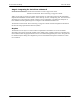
Who Should Read this Manual? About This Guide Who Should Read this Manual? The audience for this users guide is network administrators and IT support personnel who need to configure, maintain, and monitor switches and routers in a live network. However, anyone wishing to gain knowledge on the OmniSwitch 6600 series hardware will benefit from the material in this guide. When Should I Read this Manual? Read this guide as soon as you are ready to familiarize yourself with your switch hardware components.
About This Guide How is the Information Organized? How is the Information Organized? This users guide provides an overview of OmniSwitch 6600 series switches in the first chapter, an overview and procedures for setting up and managing OmniSwitch 6600 series switches in the second chapter, and an overview and procedures for setting up and managing stacks in the third chapter.
Documentation Roadmap About This Guide Stage 3: Integrating the Switch Into a Network Pertinent Documentation: OmniSwitch 6624/6648 Network Configuration Guide OmniSwitch 6624/6648 Advanced Routing Configuration Guide When you are ready to connect your switch to the network, you will need to learn how the OmniSwitch implements fundamental software features, such as 802.1Q, VLANs, and Spanning Tree.
About This Guide Related Documentation Related Documentation The following are the titles and descriptions of all the OmniSwitch 6600 series user manuals: • OmniSwitch 6600 Series Getting Started Guide Describes the hardware and software procedures for getting an OmniSwitch 6600 series switch up and running. Also provides information on fundamental aspects of OmniSwitch software and stacking architecture.
User Manual CD About This Guide User Manual CD All user guides for the OmniSwitch 6600 series are included on the User Manual CD that accompanied your switch. This CD also includes user guides for other Alcatel data enterprise products. In addition, it contains a stand-alone version of the on-line help system that is embedded in the OmniVista network management application.
1 OmniSwitch 6600 Series The OmniSwitch 6600 series switches consist of the OmniSwitch 6624 (OS6624), OmniSwitch 6600-U24 (OS6600-U24), and the OmniSwitch 6648 (OS6648). The OmniSwitch 6600 series switches are next generation enterprise edge/workgroup switches. These switches are based on the same software architecture as OmniSwitch 7000 and 8000 series switches (i.e., OS7700, OS7800, and OS8800) and are designed to meet the most stringent network requirements for mission-critical networks.
Stand-Alone and Stacked Configurations OmniSwitch 6600 Series Stand-Alone and Stacked Configurations Stand-Alone A stand-alone OmniSwitch 6600 series switch is ideal for small and medium-sized network edge applications, offering 24 or 48 10/100 ports, respectively. These switches provide support for enterprise-based devices, such as computer workstations or IP telephones.
OmniSwitch 6600 Series Availability Features Availability Features The switch provides a broad variety of Availability features. Availability features are hardware- and software-based safeguards that help prevent the loss of data flow in the unlikely event of a subsystem failure. In addition, some Availability features allow you to maintain or replace hardware components without powering off your switch or interrupting switch operations.
Availability Features OmniSwitch 6600 Series Software Rollback Software rollback (also referred to as image rollback) essentially allows the OmniSwitch 6600 series switches (in both standalone and stacked configurations) to return to a prior “last known good” version of software in the event of a system software problem. The switch controls software rollback through its resilient directory structure design (i.e., /flash/working and /flash/certified).
OmniSwitch 6600 Series Port and Fabric Capacities User-Driven Monitoring User-driven hardware monitoring refers to CLI commands that are entered by the user in order to access the current status of hardware components. The user enters “show” commands that output information to the console. Monitoring information for chassis components such as the optional back up power supply, chassis temperature sensor, and chassis fans is provided in Chapter 2, “OmniSwitch 6600 Series Chassis and Hardware Components.
Application Examples OmniSwitch 6600 Series Application Examples The following application examples show two of the many ways OmniSwitch 6600 series switches can be used in an enterprise network setting. Single Office Building with 1000 Users The following diagram shows converged voice and data applications, with 1000 users, in a single building enterprise environment. Edge devices consist of a mixture of PCs and IP telephones.
OmniSwitch 6600 Series Application Examples Medium Campus with 1500 Users This example illustrates converged voice and data applications with 1500 users spread across two buildings in an enterprise campus. Edge devices consist of a mixture of PCs and IP telephones. And, like the previous example, a single OmniPCX 4400 in the core supports IP voice initiations and terminations.
Application Examples page 1-8 OmniSwitch 6600 Series OmniSwitch 6624/6648 Hardware Users Guide April 2004
2 OmniSwitch 6600 Series Chassis and Hardware Components OmniSwitch 6600 series switches are available in five stackable chassis configurations—the 24-port OmniSwitch 6624 (OS6624) and the OmniSwitch 6600-U24 (OS6600-U24) and the 48-port OmniSwitch 6648 (OS6648). This chapter includes detailed information on each of these chassis types.
OmniSwitch 6600 Series Chassis and Hardware Components PA EX 7 NS IO STA N/ IN CK2 8 G /ACT LINK 2 OmniSwitch 6600-U24 /ACT LINK EX PA NS IO N 26 25 /ACT LINK /ACT LINK 23 21 19 24 17 24 15 23 22 13 21 20 11 19 18 9 17 16 7 4 00 h itc 66 -U2 13 12 11 9 w Om niS 15 14 5 3 1 10 8 7 6 TM 5 4 3 2 CO OK1 NS PA EX 7 2 OLE 1 L SE 1 PS 2 PS C I SE PR NS IO STA N/ IN CK2 8 G /ACT LINK 2 MP N TE FA /ACT LINK OK2 OmniSwitch 6624 20 11 18 9 16 7 24 66
OmniSwitch 6600 Series Chassis and Hardware Components OmniSwitch 6624 OmniSwitch 6624 The OS6624 is a stackable edge/workgroup switch offering 24 10/100 Ethernet ports. The OS6624 can also be equipped with up to four Gigabit Ethernet ports for connections to a high speed backbone or server.
OmniSwitch 6624 OmniSwitch 6600 Series Chassis and Hardware Components OS6624 Specifications Total number of 10/100 Mbps ports per switch 24 Total number of Gigabit Ethernet ports per switch 4 (for stand-alone switches); 2 (for stacked configurations) Total number of 10/100 Mbps ports per stack 192 (stack of eight switches) Total number of Gigabit Ethernet ports per stack 16 (stack of eight switches) Fabric capacity 7.0 Gbps full duplex; 14 Gbps aggregate Current draw Approximately 2.
OmniSwitch 6600 Series Chassis and Hardware Components OmniSwitch 6600-U24 OmniSwitch 6600-U24 The OS6600-U24 is a stackable edge/workgroup switch offering 24 fiber 100 Mbps Ethernet SFP ports. The OS6600-U24 can also be equipped with up to four Gigabit Ethernet ports for connections to a high speed backbone or server.
OmniSwitch 6600-U24 OmniSwitch 6600 Series Chassis and Hardware Components Gigabit Ethernet Uplink Module Slot The OS6600-U24 provides a dedicated slot for Gigabit Ethernet uplink modules. This slot supports the following module types: Console Port The OS6600-U24 front panel provides one RJ-45 port for console connections. Serial console connections are used by network administrators for switch management. This female RJ-45connector provides a DCE console connection.
OmniSwitch 6600 Series Chassis and Hardware Components OmniSwitch 6600-U24 OS6600-U24 Specifications Total number of 100 Mbps SFP ports per switch 24 Total number of Gigabit Ethernet ports per switch 4 (for stand-alone switches); 2 (for stacked configurations) Total number of 100 Mbps SFP ports per stack 192 (stack of eight switches) Total number of Gigabit Ethernet ports per stack 16 (stack of eight switches) Fabric capacity 7.
OmniSwitch 6600-U24 OmniSwitch 6600 Series Chassis and Hardware Components 100 Mbps Ethernet SFP Port Specifications Connector type SFP Standards supported IEEE 802.3u, IAB RFCs 826, 894 (see data sheet for more information) Data rate 100 Mbps (full or half duplex) Maximum frame size 1518 Bytes; 1522 Bytes with IEEE 802.1Q tags Connections supported 100BaseFX Cable supported SFP-100-LC-MM: 62.5/125 and 50/125 micron multimode fiber SFP-100-LC-SM: 9/125 micron single mode SFP-100-MTRJ-MM: 62.
OmniSwitch 6600 Series Chassis and Hardware Components OmniSwitch 6648 OmniSwitch 6648 The OS6648 is a stackable edge/workgroup switch offering 48 10/100 Ethernet ports. The OS6648 can also be equipped with up to four Gigabit Ethernet ports for connections to a high speed backbone or server.
OmniSwitch 6648 OmniSwitch 6600 Series Chassis and Hardware Components OS6648 Specifications Total number of 10/100 Mbps ports per switch 48 Total number of Gigabit Ethernet ports per switch 4 (for standalone switches); 2 (for stacked configurations) Total number of 10/100 Mbps ports per stack 384 (stack of eight switches) Total number of Gigabit Ethernet ports per stack 16 (stack of eight switches) Fabric capacity 10.0 Gbps full duplex; 20.0 Gbps aggregate Current draw Approximately 2.
OmniSwitch 6600 Series Chassis and Hardware Components Status LEDs Status LEDs LEDs provide visual status information. These “status lights” are used to indicate conditions such as hardware and software status, primary and back up power supply status, primary and secondary status (stacked configurations), temperature and fan errors, slot number information, link integrity, and data flow. Refer to the diagram below for detailed information on OmniSwitch 6600 series LED states. Note.
Rear Panel OmniSwitch 6600 Series Chassis and Hardware Components Rear Panel The rear panel of OmniSwitch 6600 series switches contains the following major components: • Factory-installed power supply • Back up power supply bay for optional OS66BPS-100A power supply • Connector for upcoming inline power supply (not currently supported) • Grounding block for type LCD8-10A-L grounding lug Note. OmniSwitch 6600 series switches offer the same rear panel components.
OmniSwitch 6600 Series Chassis and Hardware Components Mounting the Switch Mounting the Switch Note. If you are relocating the switch, be sure to power it down and remove all network, stacking, and power cables before moving. Airflow Considerations Be sure that your switch is placed in a well-ventilated, static-free environment. Always allow adequate clearance at the front, rear, and sides of the switch.
Mounting the Switch OmniSwitch 6600 Series Chassis and Hardware Components Installation Options There are two ways in which the OmniSwitch 6600 series switches can be installed: • Tabletop installation • Rack-mount installation Installing the Switch on a Tabletop or Bench OmniSwitch 6600 series switches can be installed freestanding as tabletop units. Place your switch in a stable, flat, static-free surface. Note. OmniSwitch 6600 series switches must be placed “right side up.
OmniSwitch 6600 Series Chassis and Hardware Components Mounting the Switch To rack-mount the switch, follow the steps below: 1 Align the holes in the provided rack-mount flanges with the four threaded holes in the OmniSwitch chassis. These threaded holes are located in the left and right sides of the chassis, near the front panel. 2 Attach the flanges to the chassis using the provided Phillips-head screws. Be sure to tighten each of the screws firmly using a Phillips screwdriver.
Mounting the Switch OmniSwitch 6600 Series Chassis and Hardware Components 7 Once the screws at the bottom of each flange are secure, install the remaining two rack mount screws. Be sure that all screws are securely tightened. Note. If you are installing multiple switches in a rack to form a stacked configuration, refer to the “Rack Mounting Stacked Configurations” section below.
OmniSwitch 6600 Series Chassis and Hardware Components Power Cords Power Cords Because the power cord is the power supply’s main disconnect device, it should be plugged into an easily accessible outlet. In the event that your power cord is lost or damaged, refer to the specifications below. Specifications The power cord to be used with 115-Volt configuration is a minimum type SJT (SVT) 18/3, rated at 250 Volts AC, 10 Amps with a maximum length of 15 feet.
Back Up Power Supply OmniSwitch 6600 Series Chassis and Hardware Components Back Up Power Supply OmniSwitch 6600 series switches provide one factory-installed power supply per chassis. Each switch also provides one bay for the optional OS66BPS-100A back up power supply. The back up power supply bay is located on the chassis rear panel (see page 2-12 for details). For information on installing a back up power supply, refer to page 2-20.
OmniSwitch 6600 Series Chassis and Hardware Components Back Up Power Supply Redundant AC Circuit Recommendation When a back up power supply is installed, it is recommended that the AC source connected to the back up power supply resides on a separate circuit from the primary power supply. With redundant AC, if a single circuit fails, the switch’s back up power supply (on a separate circuit) will likely be unaffected and the switch can continue operating. Note.
Back Up Power Supply OmniSwitch 6600 Series Chassis and Hardware Components Installing a Back Up Power Supply You can add a back up power supply to the chassis at any time without disturbing the switch’s network functions. You are not required to power down the switch. Hot Swapping Hot swapping a back up power supply refers to the action of replacing the unit while the switch is operating. Again, because it is a back up (i.e.
OmniSwitch 6600 Series Chassis and Hardware Components Back Up Power Supply 4 Grasp the front portion of the power supply and carefully insert the rear of the casing into the power supply bay. Slide the power supply back until the unit meets the connector in the chassis power supply bay. ÉR As ! ORTE DE ANCH DE COMP AFIN DEBR E EIL ION. S, AVANT APPARENTAT ION RIQUE CET ENTAT N: ON D'ALIM S ELECT NTIO CORD CHOC D'ALIM .
Back Up Power Supply OmniSwitch 6600 Series Chassis and Hardware Components Removing a Back Up Power Supply 1 Before removing the back up power supply, make sure that the power switch is in the off ( O ) position. 2 Unplug the power cord from the AC power source, as well as from the socket located on the power supply’s front panel. 3 Loosen the two captive screws, located at the left and right sides of the power supply’s front panel. If necessary, use a flat-blade screwdriver to loosen the screws. Note.
OmniSwitch 6600 Series Chassis and Hardware Components Back Up Power Supply Blank Cover Panel Requirement If you are not replacing the back up power supply being removed, be sure to install a blank cover panel (supplied with your switch) over the empty power supply bay. To install a blank cover panel, follow the steps below.
Back Up Power Supply OmniSwitch 6600 Series Chassis and Hardware Components Viewing Power Supply Status for Stacked Configurations When entering the show power command on the primary switch in a stacked configuration, you can either enter only the show power syntax or you can specify a specific slot number.
OmniSwitch 6600 Series Chassis and Hardware Components Gigabit Ethernet Uplink Modules Gigabit Ethernet Uplink Modules OmniSwitch 6624, 6600-U24, and 6648 switches support the following Gigabit Ethernet uplink modules: • OS6600-GNI-C2 Copper Gigabit Ethernet Uplink Module • OS6600-GNI-U2 Fiber Gigabit Ethernet Uplink Module OS6600-GNI-U2 The OS6600-GNI-U2 Gigabit Ethernet uplink module provides two MiniGBIC bays that support 1000BASE-X MiniGBIC transceivers.
Gigabit Ethernet Uplink Modules OmniSwitch 6600 Series Chassis and Hardware Components OS6600-GNI-U2 Uplink Module Specifications Number of ports 2 (hot-pluggable) Power Approximately 5 Watts Connector type MiniGBIC Standards supported 802.3z; 1000Base-SX, 1000Base-LX Data rate 1 Gigabit per second (full duplex) Note.
OmniSwitch 6600 Series Chassis and Hardware Components Gigabit Ethernet Uplink Modules OS6600-GNI-C2 The OS6600-GNI-C2 Gigabit Ethernet uplink module provides two fixed 1000BASE-T (copper) connections. This uplink module supports bi-directional wire speed switching on all ports simultaneously and offers a flexible solution for Gigabit Ethernet-over-copper applications. The OS6600-GNI-C2 uplink module supports multiple uplinks from the wiring closet to Gigabit Ethernet backbone links in the core.
Gigabit Ethernet Uplink Modules OmniSwitch 6600 Series Chassis and Hardware Components Stacking Module Stacking modules are used to connect OmniSwitch 6624, 6600-U24, and 6648 switches in a stack. The stack acts as a virtual chassis, with switches serving as primary and secondary management modules and Network Interface (NI) modules. For detailed information, refer to Chapter 3, “Managing OmniSwitch 6600 Series Stacks.” For information on installing stacking modules, refer to page 2-29.
OmniSwitch 6600 Series Chassis and Hardware Components Installing Uplink and Stacking Modules Installing Uplink and Stacking Modules Before installing uplink or stacking modules, refer to the important guidelines listed below: • Stacking modules can only be installed in the far-right module slot. This slot is labeled EXPANSION/ STACKING and contains port positions 27 and 28 (OS6624/6600-U24) or 51 and 52 (OS6648).
Installing Uplink and Stacking Modules OmniSwitch 6600 Series Chassis and Hardware Components 3 Slide the module back until the backplane connector is inserted in the chassis backplane; the module’s front panel should be flush with the front of the chassis. Do not force the module into the slot. Otherwise you can damage the connectors. 4 Once the module is firmly seated and flush with the chassis front panel, secure the module by tightening the two captive screws.
OmniSwitch 6600 Series Chassis and Hardware Components Removing Uplink and Stacking Modules Removing Uplink and Stacking Modules To remove an uplink or stacking module from the chassis, follow the steps below: Anti-Static Warning. Before handling any components, free yourself of static by wearing a grounding strap, or by grounding yourself properly. Static discharge can damage the switch and the uplink or stacking module.
Removing Uplink and Stacking Modules OmniSwitch 6600 Series Chassis and Hardware Components 2 Once the captive screws are completely disengaged, grasp both captive screws and slowly pull the module out of the slot.
OmniSwitch 6600 Series Chassis and Hardware Components Mini Gigabit Interface Converters (MiniGBICs) Mini Gigabit Interface Converters (MiniGBICs) Mini Gigabit Interface Converters (MiniGBICs) are fiber-based Gigabit Ethernet transceivers for use with OS6600-GNI-U2 uplink modules on OmniSwitch 6624, 6600-U24, and 6648 switches. MiniGBICs are interchangeable and hot-swappable, thus providing users an easy, flexible solution for adapting OS6600 series switches to different physical interfaces types.
Mini Gigabit Interface Converters (MiniGBICs) OmniSwitch 6600 Series Chassis and Hardware Components MiniGBIC Specifications MiniGBIC-SX Technical Specifications Connector type LC Standards supported 802.3z, 1000Base-SX Connections supported 1000Base-SX connection to backbone or server Fiber optic cable supported Multimode Source type 850 nm Output optical power -9.
OmniSwitch 6600 Series Chassis and Hardware Components Installing MiniGBICs Installing MiniGBICs Each OS6600-GNI-U2 uplink module supports up to two MiniGBICs on OmniSwitch 6624, 6600-U24, and 6648 switches. These MiniGBICs are packaged separately and therefore are not factory-installed. You can install the MiniGBIC(s) by following the steps below: Anti-Static Warning. Before handling any components, free yourself of static by wearing a grounding strap, or by grounding yourself properly.
Removing MiniGBICs OmniSwitch 6600 Series Chassis and Hardware Components 2 Push the MiniGBIC into the slot until it is completely inserted and securely seated in the OS6600-GNI-U2 module on OmniSwitch 6624, 6600-U24, and 6648 switches, as shown. G EX N PA SI / ON KIN AC ST 5 2 51 Installed MiniGBIC (OS6648 Shown) Removing MiniGBICs MiniGBICs modules can be hot swapped. You are not required to power off the switch before removing a MiniGBIC from the uplink module.
OmniSwitch 6600 Series Chassis and Hardware Components 100 Mbps SFPs (OS6600-U24) 100 Mbps SFPs (OS6600-U24) Small Form Pluggable (SFP) modules are fiber-based 100 Mbps Ethernet transceivers for use with ports 1 through 24 on OmniSwitch 6600-U24. SFPs are interchangeable and hot-swappable, thus providing users an easy, flexible solution for adapting OS6600-U24 switches to different physical interfaces types.
100 Mbps SFPs (OS6600-U24) OmniSwitch 6600 Series Chassis and Hardware Components 100 Mbps SFP Specifications SFP-100-LC-MM Technical Specifications Connector type LC Standards supported IEEE 802.3u, IAB RFCs 826, 894 (see data sheet for more information) Connections supported 100BaseFM Fiber optic cable supported multimode fiber Source type 62.5/125 and 50/125 micron Output optical power -19 to -14 dBm (62.5/125); -22.
OmniSwitch 6600 Series Chassis and Hardware Components 100 Mbps SFPs (OS6600-U24) SFP-100-MTRJ-MM Technical Specifications Connector types MTRJ Standards supported IEEE 802.3u, IAB RFCs 826, 894 (see data sheet for more information) Connections supported 100BaseFM Fiber optic cable supported multimode fiber Source type 62.
Installing SFPs (OS6600-U24) OmniSwitch 6600 Series Chassis and Hardware Components Installing SFPs (OS6600-U24) OmniSwitch 6600-U24 switches support up to 24 (twenty-four) 100 Mbps Small Form Pluggable (SFP) modules. These SFPs are packaged separately and therefore are not factory-installed. You can install the SFP(s) by following the steps below: Anti-Static Warning. Before handling any components, free yourself of static by wearing a grounding strap, or by grounding yourself properly.
OmniSwitch 6600 Series Chassis and Hardware Components Removing SFPs (OS6600-U24) Removing SFPs (OS6600-U24) SFPs modules can be hot swapped. You are not required to power off the switch before removing a SFP from the uplink module. To remove a SFP from the uplink module, follow the steps below: Anti-Static Warning. Before handling any components, free yourself of static by wearing a grounding strap, or by grounding yourself properly.
Temperature Management OmniSwitch 6600 Series Chassis and Hardware Components Temperature Management The operating temperature of your switch is an important factor in its overall health. In order to avoid a temperature-related system failure, your switch must always run at an operating temperature between 0 and 45 degrees Celsius (32 to 113 degrees Fahrenheit).
OmniSwitch 6600 Series Chassis and Hardware Components Temperature Management Viewing Temperature Status for Stacked Configurations When entering the show temperature command on the primary switch in a stacked configuration, you can either enter only the show temperature syntax or you can specify a specific slot number.
Temperature Management OmniSwitch 6600 Series Chassis and Hardware Components Temperature Errors The switch monitors the chassis ambient air temperature at all times via an onboard sensor. If an overtemperature condition occurs, there are two different levels of error severity: • Warning threshold has been exceeded • Danger threshold has been exceeded Warning Threshold If the temperature exceeds the switch’s user-configurable warning threshold, the switch sends out a trap.
OmniSwitch 6600 Series Chassis and Hardware Components Temperature Management Viewing Fan Status The switch also constantly monitors fan operation. If any of the three fans unexpectedly shuts down, the switch sends out a trap to the user and the FAN LED on the chassis front panel displays amber. Note. For detailed LED information, including the FAN LED, refer to “Status LEDs” on page 2-11. To check the current fan status, use the show fan command.
Temperature Management OmniSwitch 6600 Series Chassis and Hardware Components No Slot Number is Specified If you do not enter a slot number, fan status information for all switches in the stack displays. For example: -> show fan Chassis Fan Status -------+---+----------1 1 Running 1 2 Running 1 3 Running 2 1 Running 2 2 Running 2 3 Running 3 1 Running 3 2 Running 3 3 Running The example above shows the fan status for a stack consisting of three switches.
OmniSwitch 6600 Series Chassis and Hardware Components Temperature Management Chassis Airflow The fans pull air from the air intake vent located at the right-hand side of the chassis. The air is directed horizontally through the chassis and past the circuit board and uplink and stacking modules (if installed). Airflow is then exhausted through the fan vents at the left-hand side of the chassis. Refer to the illustrations below for more information. 1. Air Intake.
Temperature Management OmniSwitch 6600 Series Chassis and Hardware Components Blank Cover Panels Blank cover panels are provided with your switch and are used to cover empty uplink and stacking module slots, as well as empty back up power supply bays (if applicable). These cover panels play an important role in chassis airflow and temperature management.
OmniSwitch 6600 Series Chassis and Hardware Components Pinouts Pinouts 10/100 Ethernet Port – RJ-45 Pinout Pin Number Description 1 RX+ 2 RX- 3 TX+ 4 not used 5 not used 6 TX- 7 not used 8 not used Copper Gigabit Ethernet Port – RJ-45 Pinout Pin Number Description 1 BI_DB+ 2 BI_DB- 3 BI_DA+ 4 BI_DD+ 5 BI_DD- 6 BI_DA- 7 BI_DC+ 8 BI_DC- RS232 Console Port – Female DB9 Connector Pinout Pin Number Signals as DCE Console Port 1 Not used 2 RXD (from the switch) 3 TXD (
Pinouts OmniSwitch 6600 Series Chassis and Hardware Components RJ-45 Console Port – Connector Pinout Pin Number Signals as DCE Console Port 1 CTS (Clear To Send) 2 NC 3 RXD 4 GND 5 GND 6 TXD 7 NC 8 RTS (Request To Send) Shell Chassis Ground page 2-50 OmniSwitch 6600 Series Hardware Users Guide April 2004
OmniSwitch 6600 Series Chassis and Hardware Components Console Port Console Port Serial Connection to the Console Port The console port, located on the chassis front panel, provides a serial connection to the switch and is required when logging into the switch for the first time (refer to the OmniSwitch 6600 Series Getting Started Guide for more information).
Console Port OmniSwitch 6600 Series Chassis and Hardware Components 4 To change the data bits (i.e., word size) value, enter boot serialwordsize, followed by the number of data bits. Options include 7 and 8 (default). For example: Boot > boot serialwordsize 7 5 To change the stop bits value, enter boot serialstopbits, followed by the number of stop bits. Options include 1 (default) and 2.
OmniSwitch 6600 Series Chassis and Hardware Components Viewing Basic Chassis Information Viewing Basic Chassis Information This section covers the following basic chassis information and monitoring commands: show hardware info show module show module long (and show ni) show chassis show cmm Important Hardware Status Commands.
Viewing Basic Chassis Information OmniSwitch 6600 Series Chassis and Hardware Components Slot and Component Information To view basic slot position and component information, enter the show module command at the CLI prompt.
OmniSwitch 6600 Series Chassis and Hardware Components Viewing Basic Chassis Information Detailed Slot and Component Information To view more detailed slot and component information, including information on installed uplink and stacking modules, use the show module long command. Note. Because OmniSwitch 6600 series switches can also be thought of as Network Interface modules in a virtual chassis, the show ni command displays the same information as the show module long command.
Viewing Basic Chassis Information Module in slot 1 Model Name: Description: Part Number: Hardware Revision: Serial Number: Manufacture Date: Firmware Version: Admin Status: Operational Status: Power Consumption: Power Control Checksum: MAC Address: ASIC - Physical: Daughter Board in port 1 Model Name: Description: Part Number: Hardware Revision: Serial Number: Manufacture Date: Firmware Version: Admin Status: Operational Status: GBIC 1 Model Name: Description: Part Number: Hardware Revision: Serial Number:
OmniSwitch 6600 Series Chassis and Hardware Components Viewing Basic Chassis Information Basic Primary Slot and Component Information To view basic slot and component information for the base chassis only (i.e., no installed uplink or stacking modules), enter the show cmm command at the CLI prompt.
Viewing Basic Chassis Information OmniSwitch 6600 Series Chassis and Hardware Components Basic Chassis Information To view basic chassis information (i.e., no installed uplink or stacking modules), enter the show chassis command at the CLI prompt.
OmniSwitch 6600 Series Chassis and Hardware Components Managing MAC Addresses on the Switch Managing MAC Addresses on the Switch Your OmniSwitch 6600 series switch is shipped with thirty-two (32) factory-installed MAC addresses. These MAC addresses, which are stored on an EEPROM card in the chassis, are used by the switch as unique identifiers for the following functions: • Base chassis MAC address • 802.
Managing MAC Addresses on the Switch OmniSwitch 6600 Series Chassis and Hardware Components Base Chassis MAC Address as Unique Identifier The switch chassis requires a unique identifier in order to be recognized by other devices in the network. The base chassis MAC address, which is automatically allocated by the switch, serves as this identifier. The base chassis MAC address is always the start MAC address listed in the switch’s default MAC range 1.
3 Managing OmniSwitch 6600 Series Stacks In addition to working as individual stand-alone switches, OmniSwitch 6600 series switches can also be linked together to work as a single virtual switch known as a stack. With stacks you can easily expand your switching capacity simply by adding additional switches. In addition, stacks provide enhanced resiliency and redundancy features. Note.
Specifications and Default Values Managing OmniSwitch 6600 Series Stacks Specifications and Default Values The table below lists specifications for OmniSwitch 6600 series stacks. Minimum number of switches in a stack. 2 Maximum number of switches in a stack.
Managing OmniSwitch 6600 Series Stacks Stack Overview Stack Overview By default, OmniSwitch 6600 series switches operate in stand-alone mode. You can also configure two to eight OmniSwitch 6600 series switches (in any combination of OmniSwitch 6624, 6600-U24, and 6648 switches) into one large virtual chassis known as a stack. With stacks, you can easily expand your switching capacity simply by adding additional switches.
Stack Overview Managing OmniSwitch 6600 Series Stacks Stacking Resiliency and Redundancy The figure on page 3-3 shows a sample way to connect switches in a four-switch stack to ensure dualredundant connections. Except for the bottommost switch in the stack, Port 52 is connected to Port 51 on the switch below it with a 30 centimeter stacking cable. On the bottommost switch Port 52 is connected to Port 51 on the topmost switch in the stack with a 1 meter redundant stacking cable.
Managing OmniSwitch 6600 Series Stacks Stack Overview CMM Roles in a Stack When OmniSwitch 6600 series switches operate in a stack, one switch in the stack will always have a primary CMM (Chassis Management Module) software role within the stack. This switch will be responsible for functions such as software and configuration management, web-based management (i.e., WebView), SNMP management, switch diagnostics, and software rollback. Another switch will have a secondary CMM role.
Stack Overview Managing OmniSwitch 6600 Series Stacks Please note that in this example Switch 1 will assume an idle CMM role if it comes back on line.
Managing OmniSwitch 6600 Series Stacks Stack Overview Switch Logging and Monitoring Commands swlog swlog appid level swlog output show log swlog show swlog debug ktrace debug ktrace appid level debug ktrace show debug systrace debug systrace appid level debug systrace show debug systrace show log debug memory monitor debug memory monitor show log Memory Monitoring Commands show log pmd OmniSwitch 6600 Series Hardware Users Guide April 2004 page 3-7
Setting Up a Stacked Configuration Managing OmniSwitch 6600 Series Stacks Setting Up a Stacked Configuration In order to set up a new stacked OmniSwitch 6600 series configuration, you must complete the following steps, in the order they are listed: 1 Individually assign slot numbers to all switches 2 Attach all required stacking cables 3 Boot the newly-configured stack For OmniSwitch 6600 series switches, the term “slot” refers to the priority status of the switch within the stacked configuration.
Managing OmniSwitch 6600 Series Stacks Setting Up a Stacked Configuration 2 Change the slot number by gently pressing the pointed item into the SEL hole again. Each time the SEL button is pressed, the LED display increases or decreases in increments of one.
Setting Up a Stacked Configuration Managing OmniSwitch 6600 Series Stacks Slot Numbering Example 31 29 36 11 27 34 9 25 32 7 tch wi niS 30 5 24 66 28 3 12 26 1 10 35 Om TM 8 33 LE 6 SO N CO 31 4 29 2 1 OK 2 OK C SE 2 PS 36 11 27 P EM I T PR 1 PS L SE 34 9 25 32 7 N FA 30 5 4 62 6 tch wi niS 28 3 12 26 1 35 8 33 E 6 L SO N 31 4 29 2 1 OK 2 OK 1 PS 2 PS C SE L SE 34 9 25 32 7 N FA 30 5 4 62 h6 itc iSw 28 3 10 35 8 33 E 6 OL S ON 31 C 4 29 2
Managing OmniSwitch 6600 Series Stacks Setting Up a Stacked Configuration Connecting Cables to Stacking Ports On OmniSwitch 6624, 6600-U24, and 6648 switches only, note the following important guidelines before connecting stacking cables to stacking modules: • Before attempting to connect OS6624, OS6600-U24, and OS6648 switches in a stacked configuration, be sure that stacking modules are installed in the EXPANSION/STACKING slots of all switches.
Setting Up a Stacked Configuration Managing OmniSwitch 6600 Series Stacks 2 Next, attach the other end of the cable to a HSSDC connector on the switch immediately below. Repeat this procedure until all switches in the stack are connected (see illustrations a, b, and c below).
Managing OmniSwitch 6600 Series Stacks Setting Up a Stacked Configuration Redundant Stack Connection The figure below shows how the redundant connection (provided by the OS66STK-CBL1M cable) between the top and bottom switches in the stack ensures that data will continue to flow throughout the stack, even in the unlikely event of a connection failure between two switches. No Connection Failure In this example, there is a VLAN with an ingress port on switch 1 and an egress port on switch 2.
Setting Up a Stacked Configuration Managing OmniSwitch 6600 Series Stacks Booting the Stack In order for the switches in the stack to operate using their newly-assigned slot numbers, all switches in the stack must be manually booted. Important. Whenever booting a stacked configuration, note that the primary switch will automatically distribute its system and configuration software to all switches in the stack whenever the virtual chassis boots.
Managing OmniSwitch 6600 Series Stacks Setting Up a Stacked Configuration Idle Status All additional switches with higher numbers will be given idle status. The PRI and SEC LEDs for these switches will be off. Additional LED Descriptions. For complete descriptions of OmniSwitch 6600 series LED states, see “Status LEDs” on page 2-11.
Managing Switches in a Stack Managing OmniSwitch 6600 Series Stacks Managing Switches in a Stack Most Command Line Interface (CLI) commands can be used to configure OmniSwitch 6600 series switches operating in either stand-alone or stack configuration. This section describes how to use CLI commands to manage switches operating in a stack. Note. You must be logged into a switch in a stack with either the primary Chassis Management Module (CMM) or secondary CMM role to use CLI commands.
Managing OmniSwitch 6600 Series Stacks Managing Switches in a Stack Synchronizing Switches in a Stack “CMM” synchronization refers to the process of copying all files in the /flash/working and /flash/ certified directories of the switch with the primary Chassis Management Module (CMM) role to the /flash/working and /flash/certified directories of all the other switches in the stack. (This includes the switch with the secondary CMM role and all the switches with an idle CMM role.
Managing Switches in a Stack Managing OmniSwitch 6600 Series Stacks Changing the Secondary CMM Role to Primary To change a switch with a secondary role to primary use the takeover command. For example, while logged into either the primary or secondary switch enter: -> takeover at the CLI prompt. In a stack consisting of two switches the primary switch will become secondary.
Managing OmniSwitch 6600 Series Stacks Managing Switches in a Stack Resetting All Switches in a Stack To reset all switches in a stack you use the reload all command by entering -> reload all at the CLI prompt. This command can be helpful in restoring the original CMM roles in a stack (see “CMM Role Redundancy” on page 3-5).
Monitoring Stacks Managing OmniSwitch 6600 Series Stacks Monitoring Stacks As shown in the figure below, OmniSwitch 6600 series stacks can be managed and monitored with Command Line Interface (CLI) commands, WebView, SNMP, and OmniVista. See “Monitoring Stack Topology” on page 3-19 for information on monitoring stack configurations and see Chapter 2, “OmniSwitch 6600 Series Chassis and Hardware Components,” for information on monitoring and monitoring stack temperature and chassis configurations.
Managing OmniSwitch 6600 Series Stacks Monitoring Stacks In the example on the previous page there are two switches in this stack. Switch 1, which is an OS6648, has the primary CMM role and Switch 2, which is an OS6624, has the secondary CMM role. Switch 1’s left-hand stacking port (Port 51) is connected to Switch 2’s left-hand stacking port (Port 27). Switch 1’s right-hand stacking port (Port 52) is connected to Switch 2’s right-hand stacking port (Port 28).
Monitoring Stacks page 3-22 Managing OmniSwitch 6600 Series Stacks OmniSwitch 6600 Series Hardware Users Guide April 2004
A Regulatory Compliance and Safety Information This appendix provides information on regulatory agency compliance and safety for the OmniSwitch 6600 Series. Declaration of Conformity: CE Mark This equipment is in compliance with the essential requirements and other provisions of Directive 73/23/EEC and 89/336/EEC as amended by Directive 93/68/EEC.
Standards Compliance Regulatory Compliance and Safety Information Standards Compliance The product bears the CE mark. In addition it is in compliance with the following other safety and EMC standards: Safety Standards • UL 60950 • CAN/CSA-C22.2 No.
Regulatory Compliance and Safety Information Standards Compliance FCC Class A, Part 15 This equipment has been tested and found to comply with the limits for Class A digital device pursuant to Part 15 of the FCC Rules.These limits are designed to provide reasonable protection against harmful interference when the equipment is operated in a commercial environment.
Standards Compliance Regulatory Compliance and Safety Information VCCI This is a Class A product based on the standard of the Voluntary Control Council for Interference by Information Technology Equipment (VCCI). If this equipment is used in a domestic environment, radio disturbance may arise. When such trouble occurs, the user may be required to take corrective actions. Class A Warning for Taiwan and Other Chinese Markets This is a Class A Information Product.
Regulatory Compliance and Safety Information Translated Safety Warnings Translated Safety Warnings Chassis Lifting Warning Two people are required when lifting the chassis. Due to its weight, lifting the chassis unassisted can cause personal injury. Also be sure to bend your knees and keep your back straight when assisting with the lifting of the chassis. Français: Deux personnes sont priées en soulevant le châssis. En raison de son poids, le levage du châssis sans aide peut causer injury.
Translated Safety Warnings Regulatory Compliance and Safety Information Installation Warning Only personnel knowledgeable in basic electrical and mechanical procedures should install or maintain this equipment. Français: Seulement le personnel bien informé des procédures électriques et mécaniques de base devrait installer ou mettre à jour ce matériel.
Regulatory Compliance and Safety Information Translated Safety Warnings Lithium Battery Warning There is a danger of explosion if the Lithium battery in your chassis is incorrectly replaced. Replace the battery only with the same or equivalent type of battery recommended by the manufacturer. Dispose of used batteries according to the manufacturer’s instructions. The manufacturer’s instructions are as follows: Return the module with the Lithium battery to Alcatel.
Translated Safety Warnings Regulatory Compliance and Safety Information Power Disconnection Warning Your switch is equipped with multiple power supplies. To reduce the risk of electrical shock, be sure to disconnect all power connections before servicing or moving the unit. Français: Votre commutateur est équipé des alimentations d'énergie multiples. Pour réduire le risque de choc électrique, soyez sûr de débrancher toutes les connexions de puissance avant d'entretenir ou déplacer l'unité.
Regulatory Compliance and Safety Information Translated Safety Warnings Read Important Safety Information Warning The Getting Started Guide that accompanied this equipment contains important safety information about which you should be aware when working with hardware components in this system. You should read this guide before installing, using, or servicing this equipment.
Translated Safety Warnings Regulatory Compliance and Safety Information Wrist Strap Warning Because electrostatic discharge (ESD) can damage switch components, you must ground yourself properly before continuing with the hardware installation. For this purpose, Alcatel provides a grounding wrist strap and a grounding lug located near the top-right of the chassis.
Index resetting a stack 3-18 secondary 3-5 synchronizing primary and secondary commit file command 2-52 commit system command 2-52 console port 2-49, 2-50, 2-51 default settings 2-51 modifying 2-51 copy flash-synchro command 3-17 Numerics 10/100 Ethernet ports technical specifications 100 Ethernet SFP ports technical specifications 2-4, 2-10 F 2-8 fabric capacities 1-5 fans monitoring 2-45 A airflow chassis 2-47 availability 1-3 hardware monitoring 1-4 hot swapping 1-4 Smart Continuous Switching soft
Index OS6600-GNI-U2 2-25 technical specifications 2-26 OS6600-U24 see OmniSwitch 6600-U24 OS6624 see OmniSwitch 6624 OS6648 see OmniSwitch 6648 resiliency and redundancy slot numbers 3-4 specifications 3-2 topology 3-19 T P pinouts 2-49 port capacities 1-5 power cords 2-17 power supplies 2-18 back up power supply 2-18 power cords 2-17 redundant AC circuits and 2-19 R redundancy AC circuit 2-19 back up power supply 2-18 CMM roles 3-5 commands supported on secondary switch reload all command 3-18 reload