
User Guide


OmniAccess 3500 Nonstop Laptop Guardian Gateway Installation Guide
6
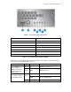
C — System Status
(on standby power)
Status LED is not used
Green Random blink HDD access
E — Disk Activity
Off Off No hard disk activity
Table 2: Function of the front control panel LEDs
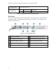
Back Panel
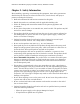
The connectors and data ports on the back panel of the gateway are shown in Figure 3
and listed in Table 3. The WAN and LAN interfaces are labeled on the back panel for
immediate identification.
Figure 3: View of the back panel
A AC power connector F USB 2.0 ports 0 and 1 (not used)
B PS 2 Mouse port (not used) G
Private Network Interface (LAN)
C Serial Port (DB9) (not used) H Video connector (not used)
D Public Network Interface (WAN) I PS2 Keyboard port (not used)
E PCI-E/X Add-in Card Slot (not used)
Table 3: Back panel connectors and data ports