
User Guide


Chapter 3. Hardware Overview
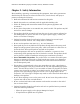
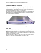
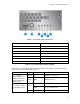
Figure 2: View of the front control panel
Item Feature
A USB 2.0 Port (not used)
B Power Button
C System Status (not used)
D System Power LED
E Hard Disk Drive Activity LED
F Public Network Interface (WAN) LED
G Private Network Interface (LAN) LED
Table 1: Front control panel buttons and LEDs
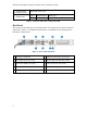
The function of the LEDs on the front control panel of the gateway (normally hidden
by the front bezel) is described in Table 2.
LED Color State Description
Green On NIC Link / no access F, G — Public
Network Interface
(WAN) and Private
Network Interface
(LAN) Activity
Green Blink Network access
On Power on
Green
Blink
Sleep / ACPI S1 state
D — Power / Sleep
(on standby power)
Off Off Power Off / ACPI S4 state
5