Part No. 060196-10, Rev. G June 2007 OmniSwitch 6800 Series Hardware Users Guide www.alcatel-lucent.
This user guide documents OmniSwitch 6800 Series hardware, including chassis and associated components. The specifications described in this guide are subject to change without notice. Copyright © 2007 by Alcatel-Lucent. All rights reserved. This document may not be reproduced in whole or in part without the express written permission of Alcatel-Lucent. Alcatel-Lucent® and the Alcatel-Lucent logo are registered trademarks of Alcatel-Lucent.
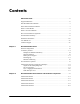
Contents About This Guide .......................................................................................................... ix Supported Platforms .......................................................................................................... ix Who Should Read this Manual? ......................................................................................... x When Should I Read this Manual? .....................................................................................
Contents Status LEDs ................................................................................................................... 2-13 10/100/1000 LEDs .................................................................................................2-14 1000 SFP LEDs ......................................................................................................2-14 10/100 LEDs ..........................................................................................................
Contents Backup Power Supply Components ..............................................................................2-39 OS6800-BPS-SHLF Backup Power Supply Shelf .................................................2-40 OS6800-BPS-SHLF Backup Power Shelf Specifications ...............................2-41 OS6800-BPS-225 225W Backup Power Supply ...................................................2-42 OS6800-BPS-225 225W Backup Power Supply Specifications .....................
Contents Reloading Switches .......................................................................................................3-25 Reloading the Primary Management Module ........................................................3-25 Reloading the Secondary Management Module ....................................................3-27 Reloading Switches with Idle Roles .......................................................................3-29 Reloading Switches in Pass-Through Mode ........................
Contents Instrucciones de seguridad en español ......................................................................... A-13 Advertencia sobre el levantamiento del chasis ............................................... A-13 Advertencia de las tapaderas en blanco .......................................................... A-13 Advertencia en caso de tormenta eléctrica ..................................................... A-13 Advertencia de instalación .......................................................
Contents viii OmniSwitch 6800 Series Hardware Users Guide June 2007
About This Guide This OmniSwitch 6800 Series Hardware Users Guide describes your switch hardware components and basic switch hardware procedures.
Who Should Read this Manual? About This Guide Who Should Read this Manual? The audience for this users guide is network administrators and IT support personnel who need to configure, maintain, and monitor switches and routers in a live network. However, anyone wishing to gain knowledge on the OmniSwitch 6800 Series hardware will benefit from the material in this guide. When Should I Read this Manual? Read this guide as soon as you are ready to familiarize yourself with your switch hardware components.
About This Guide How is the Information Organized? How is the Information Organized? This users guide provides an overview of OmniSwitch 6800 Series switches in the first chapter, an overview and procedures for setting up and managing OmniSwitch 6800 Series switches in the second chapter, and an overview and procedures for managing stacks in the third chapter.
Documentation Roadmap About This Guide Stage 3: Integrating the Switch Into a Network Pertinent Documentation: OmniSwitch 6800/6850/9000 Network Configuration Guide OmniSwitch 6800/6850/9000 Advanced Routing Configuration Guide When you are ready to connect your switch to the network, you will need to learn how the OmniSwitch implements fundamental software features, such as 802.1Q, VLANs, and Spanning Tree.
About This Guide Related Documentation Related Documentation The following are the titles and descriptions of all the OmniSwitch 6800 Series user manuals: • OmniSwitch 6800 Series Getting Started Guide Describes the hardware and software procedures for getting an OmniSwitch 6800 Series switch up and running. Also provides information on fundamental aspects of OmniSwitch software and stacking architecture.
User Manual CD About This Guide User Manual CD All user guides for the OmniSwitch 6800 Series are included on the User Manual CD. This CD also includes user guides for other Alcatel-Lucent data enterprise products. In addition, it contains a stand-alone version of the on-line help system that is embedded in the OmniVista network management application. Besides the OmniVista documentation, all documentation on the User Manual CD is in PDF format and requires the Adobe Acrobat Reader program for viewing.
1 OmniSwitch 6800 Series The OmniSwitch 6800 Series is an advanced fixed configuration family of Ethernet switches. These switches provide wire rate layer-2 forwarding and layer-3 routing with advanced services.
OmniSwitch 6800 Series • The OmniSwitch 6800-24 (OS6800-24) is a 24 port, 10/100/1000 fixed stackable chassis. • The OmniSwitch 6800-48 (OS6800-48) is a 48 port, 10/100/1000 fixed stackable chassis. This switch also supports a 10 Gigabit uplink module. • The OmniSwitch 6800-U24 (OS6800-U24) is a 24 fiber 1000 Mbps SFP connector chassis. This switch also supports a 10 Gigabit uplink module. • The OmniSwitch 6800-24L (OS6800-24L) is a 24 port fixed stackable chassis.
OmniSwitch 6800 Series Stacked Configurations Stacked Configurations In addition to working as individual, stand-alone switches, OmniSwitch 6800 Series switches (except for the OS6800-U24) can also be linked together to form a single, high-density virtual chassis known as a stack.
Availability Features OmniSwitch 6800 Series Availability Features The switch provides a broad variety of availability features. Availability features are hardware and software-based safeguards that help prevent the loss of data flow in the unlikely event of a subsystem failure. In addition, some availability features allow users to maintain or replace hardware components without powering off the switch or interrupting switch operations.
OmniSwitch 6800 Series Availability Features Software Rollback Software rollback (also referred to as image rollback) essentially allows the OmniSwitch 6800 Series switches (in both standalone and stacked configurations) to return to a prior “last known good” version of software in the event of a system software problem. The switch controls software rollback through its resilient directory structure design (i.e., /flash/working and /flash/certified).
Availability Features OmniSwitch 6800 Series Hardware Monitoring Automatic Monitoring Automatic monitoring refers to the switch’s built-in sensors that automatically monitor operations. If an error is detected (e.g., over-threshold temperature), the switch immediately sends a trap to the user. The trap is displayed on the console in the form of a text error message. (In the case of an over-threshold temperature condition, the chassis displays an amber TMP LED in addition to sending a trap.
OmniSwitch 6800 Series Port and Fabric Capacities Port and Fabric Capacities OmniSwitch 6800 Series switches offer 20 non combo 10/100/1000 Ethernet ports, 44 non combo 10/100/1000 Ethernet ports, 20 non combo 1000 Mbps SFP connectors, 20 non combo 10/100 Ethernet ports, or 44 non combo 10/100 Ethernet ports. The switches also offer combo ports, which consist of four paired Gigabit Ethernet SFP connectors and four 10/100/100 Ethernet ports.
OmniSwitch 6800 Series Application Examples OmniSwitch 6800 Series OmniSwitch 6800 Series Application Examples The following OmniSwitch 6800 Series applications are described below: • Gigabit-to-the-desktop migration • Server aggregation • Layer 3 Aggregation/Distribution • Small Enterprise core Gigabit-to-the-Desktop Migration OmniSwitch 6800 Series switches provide a migration path to Gigabit on the edge of the LAN.
OmniSwitch 6800 Series OmniSwitch 6800 Series Application Examples Server Aggregation The OmniSwitch 6800 Series switch is a well-suited server aggregation switch, especially for spaceconstrained data centers, where the switch can be installed in the same rack as the servers.
OmniSwitch 6800 Series Application Examples OmniSwitch 6800 Series Layer 3 Aggregation/Distribution OmniSwitch 6800 Series switches placed in the distribution layer of three-tier networks provide highcapacity, wire speed Layer 2 switching, Layer 3 routing, and intelligent services near the edge of the network.
OmniSwitch 6800 Series OmniSwitch 6800 Series Application Examples Small Enterprise Core With its high-speed switching capacity, supported Layer 3 routing protocols, advanced network services, and wire speed 10 Gigabit capability, the OmniSwitch 6800 Series provides effective core switching for smaller Enterprise networks (200-500 ports).
OmniSwitch 6800 Series Application Examples page 1-12 OmniSwitch 6800 Series OmniSwitch 6800 Series Hardware Users Guide June 2007
2 OmniSwitch 6800 Series Chassis and Hardware Components OmniSwitch 6800 Series switches are available in five stackable chassis configurations—the 24-port OmniSwitch 6800-24 (OS6800-24), OmniSwitch 6800-U24 (OS6800-U24), OmniSwitch 6800-24L (OS6800-24L), the 48-port OmniSwitch 6800-48 (OS6800-48), and OmniSwitch 6800-48L (OS680048L). This chapter includes detailed information on these chassis types.
OmniSwitch 6800 Series Chassis and Hardware Components OmniSwitch 6800-24 23 21 23 T /AC LINK 21 sole Con 23 21 19 24 22 17 22 24 15 24 T /AC LINK 22 13 20 18 16 14 OmniSwitch 6800-48 11 9 7 5 12 3 ed Spe 10 1 8 6 4 ed 2 Spe -24 00 tch 68 wi niS 47 Om 45 PRI OK BPS R PW TMP 47 T /AC LINK 45 sole Con 47 45 FAN 43 48 46 41 46 48 39 48 T /AC LINK 46 44 42 40 OmniSwitch 6800-U24 32 23 30 21 28 19 26 17 24 15 22 13 20 11 18 9 16 7 14 5 3 12 -4
OmniSwitch 6800 Series Chassis and Hardware Components OmniSwitch 6800-24 OmniSwitch 6800-24 The OmniSwitch 6800-24 is a stackable edge/workgroup switch offering 24 10/100/1000Base-T ports, as well as four combo SFP connectors for high speed connections.
OmniSwitch 6800-24 OmniSwitch 6800 Series Chassis and Hardware Components OS6800-24 Specifications Total 10/100/1000Base-T ports per switch 24 Total combo SFP connectors per 4 switch Total 10/100/1000Base-T ports per stack 192 (stack of eight switches) Total combo SFP connectors per 32 (stack of eight switches) stack Fabric capacity 160 Gbps Power 150W AC/DC power supply, providing +12V @ 12.
OmniSwitch 6800 Series Chassis and Hardware Components OmniSwitch 6800-48 OmniSwitch 6800-48 The OmniSwitch 6800-48 is a stackable edge/workgroup switch offering 48 10/100/1000Base-T ports, as well as four combo SFP connectors for high speed connections.
OmniSwitch 6800-48 OmniSwitch 6800 Series Chassis and Hardware Components OS6800-48 Specifications Total 10/100/1000Base-T ports per switch 48 Total combo SFP connectors per 4 switch Total 10/100/1000Base-T ports per stack 384 (stack of eight switches) Total combo SFP connectors per 32 (stack of eight switches) stack Fabric capacity 160 Gbps Power 150W AC/DC power supply, providing +12V @ 12.
OmniSwitch 6800 Series Chassis and Hardware Components OmniSwitch 6800-U24 OmniSwitch 6800-U24 The OmniSwitch 6800-U24 is an edge/workgroup switch offering 24 1000Base-X SFP connectors, as well as four combo 10/100/1000Base-T ports.
OmniSwitch 6800-U24 OmniSwitch 6800 Series Chassis and Hardware Components OS6800-U24 Specifications Total 1000Base-X SFP connectors per switch 24 Total combo 10/100/1000BaseT ports per switch 4 Fabric capacity 80 Gbps Power 150W AC/DC power supply, providing +12V @ 12.
OmniSwitch 6800 Series Chassis and Hardware Components OmniSwitch 6800-24L OmniSwitch 6800-24L The OmniSwitch 6800-24L is a stackable edge/workgroup switch offering 24 10/100Base-T ports, as well as four combo SFP connectors for high speed connections.
OmniSwitch 6800-24L OmniSwitch 6800 Series Chassis and Hardware Components OS6800-24L Specifications Total 10/100/Base-T ports per switch 20 Total 10/100/1000Base-T combo ports per switch 4 Total combo SFP connectors per 4 switch Total 10/100Base-T ports per stack 160 (stack of eight switches) Total combo SFP connectors per 32 (stack of eight switches) stack Fabric capacity 160 Gbps Power 150W AC/DC power supply, providing +12V @ 12.
OmniSwitch 6800 Series Chassis and Hardware Components OmniSwitch 6800-48L OmniSwitch 6800-48L The OmniSwitch 6800-48L is a stackable edge/workgroup switch offering 48 10/100/Base-T ports, as well as four combo SFP connectors for high speed connections.
OmniSwitch 6800-48L OmniSwitch 6800 Series Chassis and Hardware Components OS6800-48L Specifications Total 10/100Base-T ports per switch 44 Total 10/100/1000Base-T combo ports per switch 4 Total combo SFP connectors per 4 switch Total 10/100Base-T ports per stack 352 (stack of eight switches) Total combo SFP connectors per 32 (stack of eight switches) stack Fabric capacity 160 Gbps Power 150W AC/DC power supply, providing +12V @ 12.
OmniSwitch 6800 Series Chassis and Hardware Components Status LEDs Status LEDs LEDs provide visual status information. These “status lights” are used to indicate conditions such as hardware and software status, primary role status (stacked configurations), power supply status, fan and temperature errors, 10 Gigabit uplink status (when applicable), slot number information, data speed, link integrity, and activity. Refer to the diagram below for detailed information on LED states.
Status LEDs OmniSwitch 6800 Series Chassis and Hardware Components 10/100/1000 LEDs There are two LEDS on 10/100/1000 ports. The left-hand LED is the data speed LED. Displays solid green for 1000 Mbps; displays amber for 100 Mbps; off for 10 Mbps or no traffic flow. The right-hand LED is the link/activity status LED. Displays solid green when a link state exists; blinks green to show activity (transmitting or receiving traffic); off when no activity is present.
OmniSwitch 6800 Series Chassis and Hardware Components Rear Panel Rear Panel The rear panel of OmniSwitch 6800 Series switches contains the following major components: • Factory-installed power supply and power connector socket (all OmniSwitch 6800 Series switches) • Backup power supply bay for optional OS6800-BPS-225 power supply (all OmniSwitch 6800 Series switches) • Stacking ports (all OmniSwitch 6800 Series switches except for the OmniSwitch 6800-U24) • 10 Gigabit XFP module connector (all OmniSwitc
Mounting the Switch OmniSwitch 6800 Series Chassis and Hardware Components Mounting the Switch Note. If you are relocating the switch, be sure to power it down and remove all network, stacking, and power cables before moving. Airflow Considerations Be sure that your switch is placed in a well-ventilated, static-free environment. Always allow adequate clearance at the front, rear, and sides of the switch.
OmniSwitch 6800 Series Chassis and Hardware Components Mounting the Switch Chassis Airflow The fans pull air from the air intake vent located at the left-hand side of the chassis. The air is directed horizontally through the chassis and past the circuit board. Airflow is then exhausted through the fan vents at the right-hand side of the chassis. Refer to the illustrations below for more information. 1. Air Intake.
Mounting the Switch OmniSwitch 6800 Series Chassis and Hardware Components Blank Cover Panels Blank cover panels are provided with your switch and are used to cover empty backup power supply bays and 10 Gigabit uplink bays (all OmniSwitch 6800 Series switches except for the OmniSwitch 6800-24 and OmniSwitch 6800-24L). These cover panels play an important role in chassis airflow and temperature management.
OmniSwitch 6800 Series Chassis and Hardware Components Mounting the Switch Installation Options There are two ways in which the OmniSwitch 6800 Series switches can be installed: • Tabletop installation • Rack-mount installation Installing the Switch on a Tabletop or Bench OmniSwitch 6800 Series switches can be installed freestanding as tabletop units. Place your switch on a stable, flat, static-free surface. Note. OmniSwitch 6800 Series switches must be placed “right side up.
Mounting the Switch OmniSwitch 6800 Series Chassis and Hardware Components Rack-Mounting the Switch Refer to the important guidelines below before installing the OmniSwitch 6800 Series chassis in a rack. • It is recommended that two people install the switch in the rack—one person to hold the chassis and position it in the rack, and a second person to secure the chassis to the rack using attachment screws (not supplied).
OmniSwitch 6800 Series Chassis and Hardware Components Mounting the Switch 3 After the rack-mount flanges are secured to the chassis, mark the holes on the rack where the switch is to be installed. 4 Lift and position the switch until the rack-mount flanges are flush with the rack post. 5 Align the holes in the flanges with the rack holes that were marked in step 3. 6 Once the holes are aligned, insert a rack mount screw (not provided) through the bottom hole of each flange.
Setting Up a Stacked Configuration OmniSwitch 6800 Series Chassis and Hardware Components Setting Up a Stacked Configuration Rack Mounting Stacked Configurations To rack mount a stacked configuration, install all switches that are to be included in the stacked configuration as described on pages 2-20 through 2-21. Up to eight switches may be stacked to form a single virtual chassis. Note.
OmniSwitch 6800 Series Chassis and Hardware Components Setting Up a Stacked Configuration 2 Starting from the top of the stack, insert one end of the stacking cable into either stacking port A or stacking port B. The stacking port (A or B) depends on your preferred cabling pattern. Refer to Chapter 3, “Managing OmniSwitch 6800 Series Stacks” for detailed information on cabling patterns. Be sure that cable connector is completely inserted and fully seated in the chassis.
Setting Up a Stacked Configuration OmniSwitch 6800 Series Chassis and Hardware Components 5 To provide added resiliency and redundancy, you must install the redundant stacking cable to connect the top switch in the stack to the bottom switch. Connect the redundant cable now. Refer to the diagram below for more information.
OmniSwitch 6800 Series Chassis and Hardware Components Booting OmniSwitch 6800 Series Switches Booting OmniSwitch 6800 Series Switches For information on booting stand-alone switches and switches in stacked configurations, refer to the sections below. Booting a Stand-alone Switch The OmniSwitch 6800 Series switch does not use an on/off switch. The power cord is the switch’s only connect/disconnect device. The power connector socket is located on the switch’s rear panel.
Booting OmniSwitch 6800 Series Switches OmniSwitch 6800 Series Chassis and Hardware Components Booting Stacked Configurations Once the switches have been connected into a virtual chassis, the next step is to manually power on the stack. The OmniSwitch 6800 Series switch does not use an on/off switch. The power cord is the switch’s only connect/disconnect device. The power connector socket is located on the switch’s rear panel. For more information, refer to “Rear Panel” on page 2-15.
OmniSwitch 6800 Series Chassis and Hardware Components Power Cords Note. Chapter 3, “Managing OmniSwitch 6800 Series Stacks,” provides important information on virtual chassis behavior during and after a boot. Consulting this chapter is strongly recommended for users operating switches in a stacked configuration. Power Cords Because the power cord is the switch’s only disconnect device, it should be plugged into an easily accessible outlet.
Console Port OmniSwitch 6800 Series Chassis and Hardware Components Console Port The console port, located on the chassis front panel, provides a console connection to the switch and is required when logging into the switch for the first time. By default, this RJ-45 connector provides a DTE console connection.
OmniSwitch 6800 Series Chassis and Hardware Components Console Port 5 To change the stop bits value, enter boot serialstopbits, followed by the number of stop bits. Options include 1 (default) and 2.
Console Port OmniSwitch 6800 Series Chassis and Hardware Components Console Port Pinouts RJ-45 Console Port – Connector Pinout Pin Number Signals as DTE Console Port 1 NC 2 NC 3 RXD 4 Ground 5 Ground 6 TXD 7 NC 8 NC page 2-30 OmniSwitch 6800 Series Hardware Users Guide June 2007
OmniSwitch 6800 Series Chassis and Hardware Components Monitoring the Chassis Monitoring the Chassis OmniSwitch 6800 Series switches can be monitored and managed via the console port using Command Line Interface (CLI) commands. The switches can also be monitored and managed via the Ethernet ports using CLI commands, WebView, SNMP, and OmniVista. The section below provides some examples of useful hardware-related monitoring CLI commands.
Monitoring the Chassis OmniSwitch 6800 Series Chassis and Hardware Components Checking Fan Status To check the current status for all six fans in the chassis, use the show fan command. For example: -> show fan Chassis Fan Status -------+---+----------1 1 Running 1 2 Running 1 3 Running 1 4 Running 1 5 Running 1 6 Running When the show fan command is issued for a stacked configuration, status information for all switches in the stack displays.
OmniSwitch 6800 Series Chassis and Hardware Components Monitoring the Chassis Using LEDs to Visually Monitor the Chassis The front panel of OS6800-24 and OS6800-48 switches provides status LEDs that are useful in visually monitoring the status of stand-alone switches, as well as switches stacked into a virtual chassis.
OS6800-XNI-U2 10 Gigabit Expansion Module OmniSwitch 6800 Series Chassis and Hardware Components OS6800-XNI-U2 10 Gigabit Expansion Module OmniSwitch 6800-48, 6800-U24, and 6800-48L switches support a 10 Gigabit expansion module (OS6800-XNI-U2). The slot for the expansion module is located at the rear panel of the switch chassis. The 10 Gigabit Ethernet expansion module supports up to two 10 Gbps Small Form Factor Pluggable (XFP) optical transceivers.
OmniSwitch 6800 Series Chassis and Hardware Components OS6800-XNI-U2 10 Gigabit Expansion Module 10 Gigabit Slot and Port Numbering Slot Numbering The slot number for the 10 Gigabit expansion module is defined by the position of the OS6800 chassis in a stacked configuration. For example, if a switch is assigned slot 3, an expansion module installed in the same chassis is also designated slot 3. For stand-alone switches, the default slot number is 1.
OS6800-XNI-U2 10 Gigabit Expansion Module OmniSwitch 6800 Series Chassis and Hardware Components 10 GigE Interoperability Between OS6800 and OS8800 Switches In order to have 10 Gigabit uplink operability between OS6800 and OS8800 switches, users must issue the bridge port 10gig os8800optimized command on the OS6800 switch. The command must be issued separately for each 10 Gigabit port.
OmniSwitch 6800 Series Chassis and Hardware Components OS6800-XNI-U2 10 Gigabit Expansion Module Installing 10 Gigabit Expansion Modules ESD Caution. Before handling the expansion module, you must discharge all static electricity on your person to avoid Electrostatic Discharge (ESD) damage. If using a wrist strap, ensure that the wrist strap touches your skin. Attach the other end of the strap to the chassis.
OS6800-XNI-U2 10 Gigabit Expansion Module OmniSwitch 6800 Series Chassis and Hardware Components Removing 10 Gigabit Modules To remove an expansion module from the chassis, follow the steps below: ESD Caution. Before handling the expansion module, you must discharge all static electricity on your person to avoid Electrostatic Discharge (ESD) damage. If using a wrist strap, ensure that the wrist strap touches your skin. Attach the other end of the strap to the chassis.
OmniSwitch 6800 Series Chassis and Hardware Components Backup Power Supply Components Installing SFP and XFP Transceivers For information on installing XFPs and SFPs, refer to the instruction card included with the transceiver. Backup Power Supply Components OmniSwitch 6800 Series switches support optional backup power supply components.
Backup Power Supply Components OmniSwitch 6800 Series Chassis and Hardware Components OS6800-BPS-SHLF Backup Power Supply Shelf The OS6800-BPS-SHLF backup power supply shelf is a separate, rack-mountable chassis offering power supply bays for up to eight 225 watt power supply modules. Each module can be connected to a single OmniSwitch 6800 Series switch—either stand-alone or in a stacked configuration. Refer to the sections below for more information.
OmniSwitch 6800 Series Chassis and Hardware Components Backup Power Supply Components OS6800-BPS-SHLF Backup Power Shelf Specifications The table below lists the specifications for the OS6800-BPS-SHLF Backup Power Shelf: OS6800-BPS-SHLF Backup Power Shelf Specifications Width (rack-mount flanges not included) 17.32 inches, approx. Width (including rack-mount flanges) 19.125 inches, approx. Height 4.325 inches, approx. Height (rack units) 2.5 RU Depth 12 inches, approx.
Backup Power Supply Components OmniSwitch 6800 Series Chassis and Hardware Components OS6800-BPS-225 225W Backup Power Supply Up to eight OS6800-BPS-225 225 watt power supplies can be installed in the OS6800-BPS-SHLF power shelf. Each OS6800-BPS-225 provides backup power for one OS6800-24 or OS6800-48 switch. Power Connector Socket. Type IEC-320-C13. Supports one 10 amp power cord. It is recommended that you use Alcatel-Lucent provided power cords only. Air Intake Vent.
OmniSwitch 6800 Series Chassis and Hardware Components Backup Power Supply Components OS6800-BPS-225 225W Backup Power Supply Specifications The table below lists the specifications for the OS6800-BPS-225 backup power supply: OS6800-BPS-225 225W Backup Power Supply Specifications Input Voltage 3 A @ 100-240 VAC Input Frequency 50-60 Hz Width 4.3 inches, approx. Height 1.73 inches, approx. Depth 12 inches, approx.
Backup Power Supply Components OmniSwitch 6800 Series Chassis and Hardware Components Rack-Mounting the OS6800-BPS-SHLF Power Shelf Refer to the important guidelines below before installing the OS6800-BPS-SHLF power shelf in a rack. • The power shelf can be installed with either the power supply bays or the fan vents facing out. Screw holes for rack-mount flanges are provided on either side of the power shelf.
OmniSwitch 6800 Series Chassis and Hardware Components Backup Power Supply Components 3 After the rack-mount flanges are secured to the power shelf, mark the holes on the rack where the power shelf is to be installed. 4 Lift and position the power shelf until the rack-mount flanges are flush with the rack post. 5 Align the holes in the flanges with the rack holes that were marked in step 3. 6 Once the holes are aligned, insert a rack mount screw (not provided) through the bottom hole of each flange.
Backup Power Supply Components OmniSwitch 6800 Series Chassis and Hardware Components Installing a Backup Power Supply In the Power Shelf Hot-Swapping Backup Power Supplies. Backup power supplies are fully hot-swappable. In other words, you can add a backup power supply to the power shelf at any time without disturbing the switch’s network functions. You are not required to power down the switch.
OmniSwitch 6800 Series Chassis and Hardware Components Backup Power Supply Components 3 With one hand, grasp the handle at the front of the power supply. Place your other hand under the power supply casing to support its weight. Carefully insert the rear of the casing into the power supply bay and slide the power supply back along the chassis alignment guide until its connector meets the chassis backplane connector.
Backup Power Supply Components OmniSwitch 6800 Series Chassis and Hardware Components Installing the Backup Power Supply Daughtercard Once all backup power supplies are installed in the backup power supply shelf, be sure that a backup power supply daughtercard is installed in the rear panel of each switch that is to receive redundant power. For help locating the backup power supply daughtercard bay, refer to “Rear Panel” on page 2-15. Note.
OmniSwitch 6800 Series Chassis and Hardware Components Backup Power Supply Components Removing a Backup Power Supply Note. You can remove a backup power supply from the power shelf at any time without disturbing the switch’s network functions. You are not required to power down the switch. Anti-Static Warning. Before handling any components, free yourself of static by wearing a grounding strap, or by grounding yourself properly. Static discharge can damage the switch and the backup power supply.
Backup Power Supply Components OmniSwitch 6800 Series Chassis and Hardware Components 3 Once the captive screws are completely disengaged, grasp both captive screws and slowly pull the power supply out of the power supply bay. Removing the Backup Power Supply 4 Store the power supply in a secure, static-free location. 5 Refer to the important blank cover panel requirement on page 2-51.
OmniSwitch 6800 Series Chassis and Hardware Components Backup Power Supply Components Removing the Backup Power Supply Daughtercard Note. You can remove a daughtercard from the chassis at any time without disturbing the switch’s network functions. You are not required to power down the switch. Anti-Static Warning. Before handling any components, free yourself of static by wearing a grounding strap, or by grounding yourself properly. Static discharge can damage the switch and the backup power supply.
Backup Power Supply Pinouts OmniSwitch 6800 Series Chassis and Hardware Components Backup Power Supply Pinouts OS6800-BPS-225 225W Backup Power Supply Connector Pin Number 1 -50 VDC 2 Ground 3 Enable 4 RPS_ABNORMAL 5 NC OS6800-BPS-225 225W Backup Power Supply Cable Pin Number 2 Power Shelf Side Ground Pin Number Switch Side 1 -48 RTN 2 NC 3 Enable 3 Enable 2 Ground 4 -48 RTN 5 SYSPWRFAIL_L 1 -50 VDC 6 -48 DC 4 RPS_ABNORMAL 7 RPS_ABNORMAL 1 Ground 8 -48 DC 2 Enable
OmniSwitch 6800 Series Chassis and Hardware Components Viewing Primary and Backup Power Supply Status Viewing Primary and Backup Power Supply Status The switch constantly monitors primary and backup power supply operation. If either the primary or backup power source unexpectedly shuts down, the switch sends out a notification to the user. In addition, the power LED on the chassis front panel and the LED on the backup power supply front panel (if installed) display solid amber. Note.
Viewing Primary and Backup Power Supply Status OmniSwitch 6800 Series Chassis and Hardware Components No Slot Number is Specified If you do not enter a slot number, power supply information for all switches in the stack displays.
3 Managing OmniSwitch 6800 Series Stacks In addition to working as individual stand-alone switches, OmniSwitch 6800 Series switches can also be linked together to work as a single virtual chassis known as a stack. With stacks, users can easily expand their switching capacity simply by adding additional switches to the stack. In addition, stacks provide enhanced resiliency and redundancy features. For more information, refer to page 3-2. Note.
OmniSwitch 6800 Series Stack Overview Managing OmniSwitch 6800 Series Stacks OmniSwitch 6800 Series Stack Overview Users can configure up to eight OmniSwitch 6800 Series switches—in any combination of OS6800-24 and OS6800-48 chassis types—into a single virtual chassis known as a stack. With stacks, switching capacity can be easily expanded simply by adding additional switches to the stack.
Managing OmniSwitch 6800 Series Stacks Roles Within the Stack Important Note. For management module redundancy to work effectively, the software on all switches operating in the stack must be synchronized at all times. Refer to “Synchronizing Switches in a Stack” on page 3-35 for more information. Primary Secondary 1 A stack of four OmniSwitch 6800 Series switches is operating normally. The stack consists of a primary module, secondary module, and two elements operating in idle status.
Roles Within the Stack Managing OmniSwitch 6800 Series Stacks 1 A stack of two OmniSwitch 6800 Series switches is operating normally. The stack consists of a primary module and a secondary module. (The software on both elements in the stack is synchronized.) 2 The primary management module fails or is taken offline (e.g., powered off or rebooted by the user). 3 The switch operating as the secondary management module immediately takes over the primary role.
Managing OmniSwitch 6800 Series Stacks Roles Within the Stack Primary Management Module Selection In order for a stack of OmniSwitch 6800 Series switches to operate as a virtual chassis, there must be mechanism for dynamically selecting which switch within the stack will assume the primary management role. OmniSwitch 6800 Series switches use three different methods for selecting the primary switch. These methods are: • Chassis MAC address • Saved slot number • Chassis uptime Note.
Roles Within the Stack Managing OmniSwitch 6800 Series Stacks Using Saved Slot Information The saved slot number is the slot number the switch will assume following a reboot. This information is stored in a switch’s boot.slot.cfg file; the switch reads its slot number assignment from this file at bootup and assumes the specified slot number within the stack.
Managing OmniSwitch 6800 Series Stacks Roles Within the Stack Using Switch Uptime A user can override both the MAC address and saved slot methods for determining a stack’s primary management module. This is done by controlling the uptime of switches in the stack. If all elements of a stack are powered off, the user can force a particular switch to become primary by powering on that switch and waiting a minimum of 15 seconds before powering on any other switches.
Roles Within the Stack Managing OmniSwitch 6800 Series Stacks Secondary Management Module Selection In order to provide effective management module redundancy, all OmniSwitch 6800 Series stacked configurations dynamically assign a backup—or secondary—management module during the boot process. OmniSwitch 6800 Series stacks use two different methods for selecting the secondary switch.
Managing OmniSwitch 6800 Series Stacks Roles Within the Stack Using Saved Slot Information If a stack with preassigned slot information for each switch is booted, the switch with the second-lowest slot value is assigned the secondary management role. For example, if a stack of four switches is booted and the preassigned slot values for each switch are 1, 2, 3, and 4, the switch with the slot value of 2 is assigned the secondary role.
Roles Within the Stack Managing OmniSwitch 6800 Series Stacks Idle Module Role Switches that are not assigned either the primary or secondary role in a stack are, by default, assigned the role of idle modules. These idle modules operate similarly to Network Interface (NI) modules in a chassisbased switch, such as the OmniSwitch 9700/9800. It is the job of idle modules to send and receive 10/100/1000 Ethernet traffic on their ports.
Managing OmniSwitch 6800 Series Stacks Roles Within the Stack Pass-Through Mode Pass-through mode is a state in which a switch has attempted to join a stack but has been denied primary, secondary, and idle status. When a switch is in pass-through mode, its Ethernet ports are brought down (i.e, they cannot pass traffic). Its stacking cable connections remain fully functional and can pass traffic through to other switches in the stack.
Roles Within the Stack Managing OmniSwitch 6800 Series Stacks To avoid a pass-through condition following a reboot, make sure that all saved slot values for the stack are unique. Use the stack set slot command.
Managing OmniSwitch 6800 Series Stacks Roles Within the Stack To resolve this pass-through condition, simply assign slot 1001 a new saved slot value and reboot the module.
Roles Within the Stack Managing OmniSwitch 6800 Series Stacks In some pass-through conditions (for example, larger stacks where multiple switches are in pass-through mode), it might be desirable to correct any duplicate saved slot assignments and then reboot the entire stack. The recovery from pass-through can be accomplished with fewer steps than reassigning slot numbers and rebooting modules on a slot-by-slot basis.
Managing OmniSwitch 6800 Series Stacks Stack Cabling Stack Cabling Switches are connected to each other in a stack with stacking cables. These stacking cables provide highspeed, dual-redundant links between switches in a stack. Stacking cables for OmniSwitch 6800 Series switches can be connected in any pattern. In other words, the cable connected to stacking port A of one switch can be connected to either stacking port A or stacking port B of the adjacent switch.
Stack Cabling Managing OmniSwitch 6800 Series Stacks Redundant Stacking Cable Connection OmniSwitch 6800 Series switches allow redundant stacking cable connections between the top-most and bottom-most switches in a stack. Important. For a stacked configuration to have effective redundancy, a redundant stacking cable must be installed between the upper-most and bottom-most switch in the chassis at all times.
Managing OmniSwitch 6800 Series Stacks Stack Cabling Redundant stacking cables provide a form of dual redundancy. As shown in the figure above, the redundant cable allows traffic to flow in the event of a stacking link failure. The redundant cable also provides failover if a switch goes down within the stack.
Slot Numbering Managing OmniSwitch 6800 Series Stacks Slot Numbering For a stack of OmniSwitch 6800 Series switches to operate as a virtual chassis, each module in the stack must be assigned a unique slot number. To view the current slot assignments for a stack, use the show ni or show module commands. The slot number is also displayed on the front panel of each switch by the LED located on the right side of the chassis (refer to “Status LEDs” on page 2-13 for more information).
Managing OmniSwitch 6800 Series Stacks Slot Numbering If the switch with the lowest MAC address happens to be the bottom-most module in the stack, slot numbering will not resume from the top of the stack. Instead, the system software will select the secondary module using the standard method (i.e., the switch connected to the primary’s stacking port A), then continue to number the stack from the bottom up. This intuitive slot assignment provides the cleanest and most manageable stack topology.
Slot Numbering Managing OmniSwitch 6800 Series Stacks Manual Slot Number Assignment To manually assign slot numbers to one or more modules in a stack, use the stack set slot command. This command writes slot information to the boot.slot.cfg file located in a switch’s /flash directory. It is this saved slot information that the switch will assume following a reboot.
Managing OmniSwitch 6800 Series Stacks Slot Numbering When the stack comes up following the reboot, the manually-configured slot numbers display as follows: Slot 1 - Primary Slot 2 - Secondary Slot 3 - Idle Slot 4 - Idle Slot 5 - Idle Slot 6 - Idle Slot 7 - Idle Slot 8 - Idle Note. The stack set slot command can also be used to manually correct duplicate saved slot assignments within the stack topology. Refer to pages 3-11 through 3-13 for detailed information.
Hot-Swapping Modules In a Stack Managing OmniSwitch 6800 Series Stacks Hot-Swapping Modules In a Stack As with chassis-based switches such as the OmniSwitch 9700/9800, NI modules within an OmniSwitch 6800 Series virtual chassis are hot-swappable. NI modules are essentially those modules operating in the stack in idle mode. These modules can be removed from, or added to, an existing stack without disrupting other modules in the stack.
Managing OmniSwitch 6800 Series Stacks Hot-Swapping Modules In a Stack Merging Stacks Merging stacks involves connecting two or more operational stacks and attempting to reboot them as a single virtual chassis. In most cases, errors will result. To merge stacks without causing errors, select one stack that is to remain up and running and then add modules from the other stack(s) by following the steps below: 1 Make sure all switches are running the same software version.
Understanding Tokens Managing OmniSwitch 6800 Series Stacks Understanding Tokens OmniSwitch 6800 and OmniSwitch 6800L switches use global module identifiers—referred to as tokens— for budgeting stack ASIC resources. Each stack offers 32 tokens, with each module added to the stack using a specific number of these tokens. For a list showing the number of tokens used by each module type, refer to the table below.
Managing OmniSwitch 6800 Series Stacks Reloading Switches Reloading Switches Reloading is essentially a soft boot of a switch. Users can reload stacked modules operating in any role— i.e., primary, secondary, idle, and pass-through. Refer to the sections below for more information. Reloading the Primary Management Module If the switch with the primary management role is reloaded, the switch with the secondary role automatically takes over primary management functions.
Reloading Switches Managing OmniSwitch 6800 Series Stacks If there are only two switches in the stack, the switch that was reloaded (the former primary) assumes the secondary role when it comes back up. 1 In this stack of two OmniSwitch 6800 Series switches, the slot 1 Primary - Slot 1 switch is the primary management module. The slot 2 switch is the secondary. Secondary - Slot 2 -> reload primary 2 The user reloads the stack’s primary management module by issuing the reload primary command.
Managing OmniSwitch 6800 Series Stacks Reloading Switches Reloading the Secondary Management Module If the switch with secondary management role is reloaded, the idle switch with the lowest slot number will automatically assume the secondary role. The reloaded switch (the former secondary) will assume an idle role when it comes back up. Meanwhile, the switch with the primary management role, as well as any other idle modules in the stack, continue operations without interruption.
Reloading Switches Managing OmniSwitch 6800 Series Stacks If there are only two switches in the stack, the switch that was reloaded (the former secondary) resumes the secondary role when it comes back up. Primary - Slot 1 Secondary - Slot 2 -> reload secondary 1 In this stack of two OmniSwitch 6800 Series switches, the slot 1 switch is the primary management module. The slot 2 switch is the secondary. 2 The user reloads the stack’s secondary management module by issuing the reload secondary command.
Managing OmniSwitch 6800 Series Stacks Reloading Switches Reloading Switches with Idle Roles Similar to reloading Network Interface (NI) modules on chassis-based switches such as the OmniSwitch 9700/9800, modules operating in idle status within a stack can be reloaded via the CLI. Note. Any traffic being passed on the module’s Ethernet ports will be interrupted during the reboot. Other modules within the stack will continue to operate without interruption.
Reloading Switches Managing OmniSwitch 6800 Series Stacks Reloading All Switches in a Stack Reloading all switches in the stack is essentially a full reboot of the virtual chassis. This can be useful in restoring a stack’s previously configured topology—i.e., the stack’s saved slot numbers and management roles. Note, however, that all data flow on the stack is interrupted whenever a full reboot is issued. To reset all switches in a stack use the reload all command. For example: -> reload all Important.
Managing OmniSwitch 6800 Series Stacks Reloading Switches No Switches In the Stack Have Saved Slot Information If a full reload is issued and no switches in the stack have unique slot numbers, slot numbers will be assigned beginning with the switch with the lowest MAC address. (This can occur if the boot.slot.cfg file has been deleted from each switch’s /flash directory—e.g., by issuing the stack clear slot command for all modules in the stack.
Reloading Switches Managing OmniSwitch 6800 Series Stacks Avoiding Split Stacks The term “splitting” a stack refers to the creation of isolated modules within the virtual chassis. A split stack can result from the following conditions: • Two or more non-adjacent switches are reloaded simultaneously • The stack is reloaded without a redundant stacking cable connection The sections below offer simple guidelines for avoiding splitting the stack during the reload process.
Managing OmniSwitch 6800 Series Stacks Changing the Secondary Module to Primary Changing the Secondary Module to Primary OmniSwitch 6800 Series stacks allow users to manually force the secondary switch to assume the primary management role. This is referred to as “takeover.” The behavior of a takeover is similar to that of reloading the primary management module (see page 3-25). Whenever a takeover is initiated, the switch with the secondary role automatically takes over primary management functions.
Changing the Secondary Module to Primary Managing OmniSwitch 6800 Series Stacks If there are only two switches in the stack, the former primary switch resumes the secondary role when it comes back up following the takeover. Primary - Slot 1 Secondary - Slot 2 -> takeover 1 In this stack of two OmniSwitch 6800 Series switches, the slot 1 switch is the primary management module. The slot 2 switch is the secondary.
Managing OmniSwitch 6800 Series Stacks Synchronizing Switches in a Stack Synchronizing Switches in a Stack Management module synchronization refers to the process of copying all files in the /flash/working and /flash/certified directories of the primary management module to the /flash/working and /flash/certified directories of all the other switches in the stack. The system and configuration software on the nonprimary switches—i.e.
Monitoring the Stack Managing OmniSwitch 6800 Series Stacks Monitoring the Stack As shown in the previous sections, monitoring the current status and operation of all elements in a stack can help users avoid unexpected stack conditions. The table below includes CLI commands that are useful in monitoring stack conditions. CLI Commands Used for Monitoring a Stack show stack topology Displays the current operating topology of switches within a stack.
Managing OmniSwitch 6800 Series Stacks Monitoring the Stack CLI Commands Supported on Both Primary and Secondary Management Modules Although most CLI commands are executed when logged into the switch with the primary management role, there is a group of commands that is supported when logged in to either the primary or secondary management module. For a list of these commands, refer to the tables below. Note.
Monitoring the Stack page 3-38 Managing OmniSwitch 6800 Series Stacks OmniSwitch 6800 Series Hardware Users Guide June 2007
A Regulatory Compliance and Safety Information This appendix provides information on regulatory agency compliance and safety for the OmniSwitch 6800 Series. Declaration of Conformity: CE Mark This equipment is in compliance with the essential requirements and other provisions of Directive 73/23/EEC and 89/336/EEC as amended by Directive 93/68/EEC.
China RoHS: Hazardous Substance Table Regulatory Compliance and Safety Information China RoHS: Hazardous Substance Table 产品说明书附件 SUPPLEMENT TO PRODUCT INSTRUCTIONS 这个文件涉及的是在中华人民共和国境内进口或销售的电子信息产品 Include this document with all Electronic Information Products imported or sold in the People’s Republic of China 部件名称 (Parts) 电路模块 (Circuit Modules) 电缆及电缆组件 (Cables & Cable Assemblies) 金属部件 (Metal Parts) 塑料和聚合物部件 (Plastic and Polymeric parts) 铅 (Pb) 有毒有害物质或元素 (Hazardous Substance) 多溴联苯 汞 镉 六价铬 6+ (PBB) (Hg)
Regulatory Compliance and Safety Information China RoHS: Hazardous Substance Table Products are packaged using one or more of the following packaging materials: CB Corrugated Cardboard FB Corrugated Fiberboard OmniSwitch 6800 Series Hardware Users Guide June 2007 Low-Density Polyethylene page A-3
Standards Compliance Regulatory Compliance and Safety Information Standards Compliance The product bears the CE mark. In addition it is in compliance with the following other safety and EMC standards: Safety Standards • UL 60950 • CAN/CSA-C22.2 No.
Regulatory Compliance and Safety Information Standards Compliance Stacks consisting of two to eight OmniSwitch 6800 Series switches comply with Class A requirements. FCC Class A, Part 15 This equipment has been tested and found to comply with the limits for Class A digital device pursuant to Part 15 of the FCC Rules.These limits are designed to provide reasonable protection against harmful interference when the equipment is operated in a commercial environment.
Standards Compliance Regulatory Compliance and Safety Information VCCI This is a Class A product based on the standard of the Voluntary Control Council for Interference by Information Technology Equipment (VCCI). If this equipment is used in a domestic environment, radio disturbance may arise. When such trouble occurs, the user may be required to take corrective actions. Class A Warning for Taiwan and Other Chinese Markets This is a Class A Information Product.
Regulatory Compliance and Safety Information Translated Safety Warnings Translated Safety Warnings Chassis Lifting Warning Two people are required when lifting the chassis. Due to its weight, lifting the chassis unassisted can cause personal injury. Also be sure to bend your knees and keep your back straight when assisting with the lifting of the chassis. Français: Le châssis doit être soulevé par deux personnes au minimum.
Translated Safety Warnings Regulatory Compliance and Safety Information Installation Warning Only personnel knowledgeable in basic electrical and mechanical procedures should install or maintain this equipment. Français: Toute installation ou remplacement de l'appareil doit être réalisée par du personnel qualifié et compétent. Deutsch: Dieses Gerät soll nur von Personal installiert oder gewartet werden, welches in elektrischen und mechanischen Grundlagen ausgebildet ist.
Regulatory Compliance and Safety Information Translated Safety Warnings Lithium Battery Warning There is a danger of explosion if the Lithium battery in your chassis is incorrectly replaced. Replace the battery only with the same or equivalent type of battery recommended by the manufacturer. Dispose of used batteries according to the manufacturer’s instructions. The manufacturer’s instructions are as follows: Return the module with the Lithium battery to Alcatel-Lucent.
Translated Safety Warnings Regulatory Compliance and Safety Information Power Disconnection Warning Your switch is equipped with multiple power supplies. To reduce the risk of electrical shock, be sure to disconnect all power connections before servicing or moving the unit. Français: Il se peut que cette unité soit équipée de plusieurs raccordements d'alimentation. Pour supprimer tout courant électrique de l'unité, tous les cordons d'alimentation doivent être débranchés.
Regulatory Compliance and Safety Information Translated Safety Warnings Read Important Safety Information Warning The Getting Started Guide that accompanied this equipment contains important safety information about which you should be aware when working with hardware components in this system. You should read this guide before installing, using, or servicing this equipment.
Translated Safety Warnings Regulatory Compliance and Safety Information Wrist Strap Warning Because electrostatic discharge (ESD) can damage switch components, you must ground yourself properly before continuing with the hardware installation. For this purpose, Alcatel-Lucent provides a grounding wrist strap and a grounding lug located near the top-right of the chassis.
Regulatory Compliance and Safety Information Instrucciones de seguridad en español Instrucciones de seguridad en español Advertencia sobre el levantamiento del chasis Se requieren dos personas para levantar el chasis. Debido a su peso, la elevación del chasis sin ayuda puede causar daños corporales. También es seguro doblar sus rodillas y guardar su espalda derecho al ayudar a levantar el chasis.
Instrucciones de seguridad en español Regulatory Compliance and Safety Information Advertencia sobre una apropiada conexión a tierra Para evitar peligro de descargas: • El cable de alimentación debe estar conectado a una toma de alimentación adecuadamente cableada y con toma de tierra. Cualquier equipo al cual se conecte este producto debe estar también conectado a tomas de alimentación adecuadamente cableadas.
Index CLI commands supported on secondary switch 3-37 console port 2-28, 2-30 default settings 2-28 modifying default settings 2-28 F fabric capacities Numerics 10 Gigabit expansion module 2-34 technical specifications 2-34 tokens 2-35 H hardware monitoring 1-6, 2-31, 3-36 automatic 1-6 LEDs 1-6, 2-13, 2-26, 2-33 user-driven 1-6 hot swapping 1-5, 2-46, 3-22 modules in a stack 3-22 A availability 1-4 hardware monitoring 1-6, 3-36 hot swapping 1-5 management module redundancy software rollback 1-5 1-7
Index OS6800-48L see OmniSwitch 6800-48L OS6800-BPS see backup power supply OS6800-BPS-SHLF see backup power shelf OS6800-U24 see OmniSwitch 6800-U24 OS6800-XNI-U2 see 10 Gigabit expansion module P pass-through modules 3-11 reloading 3-29 pinouts 2-30, 2-52 port capacities 1-7 power cords 2-27 primary management module dynamic selection 3-5 reloading 3-25 T takeover command 3-33 technical specifications 10 Gigabit expansion module 2-34 backup power shelf 2-41 backup power supply 2-43 console port 2-28, 2