
User guide


OmniSwitch 6800 Series Chassis and Hardware Components Rear Panel
OmniSwitch 6800 Series Hardware Users Guide June 2007 page 2-15
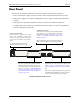
Rear Panel
The rear panel of OmniSwitch 6800 Series switches contains the following major components:
• Factory-installed power supply and power connector socket (all OmniSwitch 6800 Series switches)
• Backup power supply bay for optional OS6800-BPS-225 power supply (all OmniSwitch 6800 Series
switches)
• Stacking ports (all OmniSwitch 6800 Series switches except for the OmniSwitch 6800-U24)
• 10 Gigabit XFP module connector (all OmniSwitch 6800 Series switches except for the OmniSwitch
6800-24 and OmniSwitch 6800-24L)
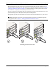
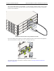
OmniSwitch 6800 Series Rear Panel
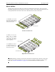
Stacking Ports A and B
Connector ports for use in stacking OmniSwitch 6800
Series switches into a virtual chassis. For detailed
information on stacking switches, refer to page 2-22,
as well as “Managing OmniSwitch 6800 Series
Stacks” on page 3-1.
Note: The OS6800-U24 does not support stacking. On
these switches, this section of the rear panel is blank.
Stack A Stack B
Backup Power Supply Bay
Slot for optional user-installable OS6800-
BPS-225 backup power supply connector. For
more information on the backup power supply,
refer to the sections, “OS6800-BPS-SHLF
Backup Power Supply Shelf” on page 2-40
and “OS6800-BPS-225 225W Backup Power
Supply” on page 2-42.
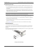
Power Connector Socket
Type IEC-320-C13. Supports one 10 amp
power cord. OmniSwitch 6800 Series
switches do not provide on/off switches; the
power cord is the switch’s only disconnect
device.
It is recommended that you use only
Alcatel-Lucent provided power cords.
10 Gigabit XFP Module Slot
Reserved for use with two-port 10 Gigabit XFP
module. Refer to “OS6800-XNI-U2 10 Gigabit
Expansion Module” on page 2-34 for more informa-
tion.
Note: The 10 Gigabit XFP Module is not supported
on OS6800-24 and OS6800-24L switches. On these
switches, this section of the rear panel is blank.