
User guide


Mounting the Switch OmniSwitch 6800 Series Chassis and Hardware Components
page 2-16 OmniSwitch 6800 Series Hardware Users Guide June 2007
Mounting the Switch
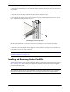
Note. If you are relocating the switch, be sure to power it down and remove all network, stacking, and
power cables before moving.
Airflow Considerations
Be sure that your switch is placed in a well-ventilated, static-free environment. Always allow adequate
clearance at the front, rear, and sides of the switch.
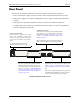
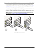
The following diagram shows recommended minimum clearances for adequate chassis airflow and access
to components at the rear of the chassis—e.g., backup power supply connectors and power cord(s).
OmniSwitch 6800 Series Chassis Top View
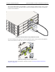
Note. Never obstruct the air vents located at the sides of the chassis. Obstructing these vents can cause
switch failure. Clearance is not required at the top and bottom of the chassis. For detailed chassis airflow
diagrams, refer to “Chassis Airflow” on page 2-17.
}
Rear Recommended 5 inches
minimum at rear of chassis for
access to backup power supply
connectors and power cord(s).
Sides 2 inches minimum at left
and right sides for adequate air-
flow. For detailed information on
chassis airflow, refer to page 2-17.
Front Recommended 6 inches
minimum at front of chassis for
access to LEDs and network
cables.
}