
User guide


OmniSwitch 6800 Series Chassis and Hardware Components Mounting the Switch
OmniSwitch 6800 Series Hardware Users Guide June 2007 page 2-21
3 After the rack-mount flanges are secured to the chassis, mark the holes on the rack where the switch is
to be installed.
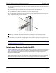
4 Lift and position the switch until the rack-mount flanges are flush with the rack post.
5 Align the holes in the flanges with the rack holes that were marked in step 3.
6 Once the holes are aligned, insert a rack mount screw (not provided) through the bottom hole of each
flange. Tighten both screws until they are secure.
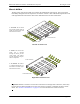
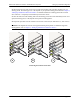
Attaching the Switch to the Rack
Note. Be sure to install the screws in the bottom hole of each flange, as shown, before proceeding.
7 Once the screws at the bottom of each flange are secure, install the remaining two rack mount screws.
Be sure that all screws are securely tightened.
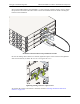
Note. If you are installing multiple switches in a rack to form a stacked configuration, refer to “Setting Up
a Stacked Configuration” on page 2-22.
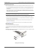
Installing and Removing Combo Port SFPs
OmniSwitch 6800 Series switches offer four Gigabit Ethernet combo ports, located on the front panel (see
page 2-3 and page 2-5). These combo ports support hot-swappable fiber Small Form-Factor Pluggables
(SFPs). For instructions on installing and removing combo port SFPs, refer to the instruction card
provided with the SFP product.
Note. Combo port preferences are user-configurable via the system software. Refer to the “Configuring
Ethernet Ports” in the OmniSwitch 6800 Series Network Configuration Guide for complete details.
2
2
2
4
2
1
2
3
2
1
2
3
2
2
2
4
Co n s ol e
1
5
1
6
1
7
1
8
1
9
2
0
2
1
2
2
2
3
L
IN
K
/A
C
T
2
4
L
IN
K
/
A
C
T
1
3
1
4