® OmniSwitch 7700/7800 Getting Started Guide 060130-10, Rev.
Warning. Only personnel knowledgeable in basic electrical and mechanical procedures should install or maintain this equipment. Lithium Batteries Caution. There is a danger of explosion if the Lithium battery in your chassis is incorrectly replaced. Replace the battery only with the same or equivalent type of battery recommended by the manufacturer. Dispose of used batteries according to the manufacturer’s instructions.
Table of Contents OmniSwitch 7700/7800 . . . . . . . . . . . . . . . 1 Features . . . . . . . . . . . . . . . . . . . . . . . . . . . . . . . . . . . 1 Availability Features . . . . . . . . . . . . . . . . . . . . . . 1 Chassis Types . . . . . . . . . . . . . . . . . . . . . . . . . . . . . . 2 OmniSwitch 7700 . . . . . . . . . . . . . . . . . . . . . . . . 2 OmniSwitch 7800 . . . . . . . . . . . . . . . . . . . . . . . . 3 Installing the Hardware ............... 4 Items Required . . . . . . . . . . .
Setting the Date and Time . . . . . . . . . . . . . . . . . . . 24 Files and Directories . . . . . . . . . . . . . . . . . . . . 36 Setting Optional System Information . . . . . . . . . . . . . . . . . . . . . . . . . . . . . . . 25 Specifying an Administrative Contact . . . . . . . 25 Specifying a System Name . . . . . . . . . . . . . . . . 25 Specifying the Switch’s Location . . . . . . . . . . . 25 Boot and Image Files . . . . . . . . . . . . . . . . . . . . . . . . . . . 36 Viewing Your Changes . .
Troubleshooting . . . . . . . . . . . . . . . . . . . . . . . . . . . 47 The WebView login screen does not display. . . . . . . . . . . . . . . . . . . . . . . . . . . . 47 The login screen displays, but my login attempt fails. . . . . . . . . . . . . . . . . . . . . . . . 47 Hardware Basics . . . . . . . . . . . . . . . . . . . . . . . . 48 Chassis Slot Numbering . . . . . . . . . . . . . . . . . . . . . 48 Chassis Management Module (CMM) . . . . . . . . . . . . . 49 CMM Redundancy . . . . . . . . . . .
vi March 2005
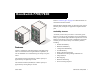
OmniSwitch 7700/7800 Refer to “Chassis Types” on page 2 for additional details on OS7700 and OS7800 switches. TM Om niSw itch Both half duplex and full duplex are supported on all 10/100 Ethernet ports; full duplex is supported on Gigabit Ethernet ports.
For more information on Availability features, refer to your Hardware Users Guide, Switch Management Guide, and Network Configuration Guide. Chassis Types OmniSwitch 7700 The OmniSwitch 7700 is a 10-slot edge or small enterprise core switch. The OmniSwitch 7700 offers up to 192 10/100 Ethernet ports and can also be equipped with up to 96 Gigabit Ethernet ports.
OmniSwitch 7800 The OmniSwitch 7800 is an 18-slot switch designed for the medium enterprise core or large wiring closet. The OmniSwitch 7800 offers up to 384 10/100 Ethernet ports. Alternatively, it can be equipped with up to 192 Gigabit Ethernet ports.
Installing the Hardware Items Required • Grounding wrist strap (included) Electrical Requirements OmniSwitch 7700/7800 switches have the following general electrical requirements: • Phillips screwdriver • Each switch requires one grounded electrical outlet for • Flat-blade screwdriver • Serial cable Site Preparation Environmental Requirements OmniSwitch 7700/7800 switches have the following environmental and airflow requirements: • The installation site must maintain a temperature between 0° and 45° Cel
Weight Considerations Unpacking and Installing the Switch When fully-populated (i.e., with all CMM and NI modules and power supplies installed), the OmniSwitch 7700 weighs approximately 128 lbs (58 Kgs); the OmniSwitch 7800 weighs approximately 188 lbs (85 Kgs). Unpacking the Chassis Items Included To protect your switch components from electrostatic discharge (ESD) and physical damage, read all unpacking recommendations and instructions carefully before beginning.
4 The overpack is the outer shell of the packaging. Lift the overpack straight up until it slides free from the rest of the packaging. This allows easy access to the chassis. TE ER MP 50100/ /60H11 5/ z, 250V 8.0/ 7.0/ 3.5 A 3.5 A 5 Carefully remove the protective plastic from the switch chassis. 6 In order to reduce the weight of the chassis, it is recommended that you remove all factory-installed power supplies prior to lifting it from the packaging.
Lifting the Chassis TE R MP 50100/ /60H11 5/ z, 250V 8.0/ 7.0/ 3.5 AC DC A Important. Two people are required when lifting the chassis. Due to its weight, lifting the chassis unassisted can cause personal injury. OK O OV K TE ER MP 50100/ /60H11 5/ z, 250V 8.0/ 7.0/ 3.5 Once its weight has been reduced by removing the power supplies, the chassis can be lifted from the packaging material and moved to the location where it is to be installed (see important note below).
Rack-Mounting } Rear. 6 inches minimum at rear of chassis fan unit. Refer to the important guidelines below before installing the OmniSwitch chassis in a rack. • Rack-mounting the chassis requires three people—two Sides. 2 inches minimum at left and right sides. people to hold the chassis and position it in the rack and a third person to secure the chassis to the rack using the attachment screws. • The chassis has two integral rack-mount flanges that } Front. 6 inches minimum at front of chassis.
2 Using two people, lift and position the chassis until the 5 Once the screws at the bottom of each flange are rack-mount flanges are flush with the rack post. secure, install the remaining screws. Be sure that all screws are securely tightened. 3 Align the holes in the flanges with the rack holes you marked in step 1. 4 Once the holes are aligned, use a third person to insert a screw through the bottom hole on each flange. Tighten both screws until they are secure.
Standalone Installing Power Supplies The OmniSwitch 7700/7800 can be installed unmounted as a standalone unit. Be sure that the installation location is a stable, flat surface that can accommodate the fully-populated weight of all switches being installed. One fully-populated OmniSwitch 7700 weighs approximately 128 lbs (58 Kgs); a fully-populated OmniSwitch 7800 weighs approximately 188 lbs (85 Kgs). Next, reinstall the power supplies in the chassis power supply bays by following the steps below. Note.
4 Continue sliding the power supply back until the front 8 Once the power cord is looped through the retainer, panel meets the front of the chassis. Do not force the power supply into the bay. Otherwise you can damage the connectors. plug the power cord connector into the power supply’s socket and then plug the power cord into an easily-accessible, properly grounded outlet. Do not use an extension cord. 5 Tighten the two captive screws, located at the top and bottom of the power supply’s front panel.
Using the Grounding Wrist Strap and Chassis Grounding Lug Because electrostatic discharge (ESD) can damage switch components such as the Network Interface (NI) and CMMs, you must ground yourself properly before continuing with the hardware installation. For this purpose, Alcatel provides a grounding wrist strap and a grounding lug located near the bottom-right of the chassis. To properly ground yourself, follow the steps below. Note. The grounding lug diagram at left is a general diagram only.
Installing the Network Interface (NI) and Chassis Management Modules (CMMs) Once you are properly grounded, you may begin installing the Network Interface (NI) and CMM(s). NI Modules NI modules may be installed in any slot position from 1 through 8 in OS7700 switches and 1 through 16 in OS7800 switches. CMMs CMMs may be installed in slots A or B in OS7700 and OS7800 switches. A minimum of one CMM is required for switch operations; the second CMM provides redundancy.
2 The module should slide in easily. Do not force the 4 Once the module is firmly seated, secure the module to module into the slot. If any resistance is encountered, ensure the module is aligned properly in the card guide. Also, see the important note regarding chassis card guides on page 13. the chassis by tightening the two captive screws. Be sure not to overtighten the captive screws. If you use a screwdriver, the torque used to tighten the screws must not exceed 2.3 inch pounds.
Installing GBIC Connectors If you are installing an OS7-GNI-U2 module, you must install Gigabit Interface Converters (GBICs) as required. OS7-GNIU2 modules provide ports for up to two GBICs. These GBICs are packaged separately. Caution. Do not force the GBIC into the slot. If the GBIC does not slide easily into position, verify that the GBIC grooves are aligned properly. Forcing the GBIC into the slot can damage the unit, as well as components on your GNI module.
Note. The diagram below is a representation only; the physical appearance of the actual MiniGBIC may vary. Blank cover plates are factory-installed in the chassis and are used to cover empty CMM and NI slots, as well as empty power supply bays. 6 7 8 These cover plates play an important role in chassis airflow and temperature management. They also provide protection for module processor boards and other sensitive internal switch components by closing off a chassis that is not fully populated.
Connections and Cabling Once your switch is properly installed, you should connect all network and management cables required for your network applications.
Ethernet Management Port (EMP) Cable Requirements Refer to the diagram below for console/modem port and EMP locations. There are specific cable type requirements (i.e., straightthrough or crossover) based on the location of the Ethernet Management Port (EMP) and the type of device to which it is connecting.
Booting the Switch Now that you have installed the switch components and connected all required cables, you can boot the switch. To boot the switch, simply turn the on/off switch for all installed power supplies to the on ( | ) position. Note. If you have more than one power supply installed, be sure to turn on each power supply in rapid succession, (i.e., within a few seconds of each other). This ensures that there will be adequate power for all NI modules when they boot.
Your First Login Session In order to complete the setup process for the switch, you should complete the following steps during your first login session: • Log in to the switch Logging In to the Switch When you first log in to the switch, you will be prompted for a login (i.e., user) name and password. During this first login session, only one user name option and one password option is available: • Set IP address information for the Ethernet Management Port (EMP) • Login (i.e.
More Information On User Accounts. A user account includes a login name, password, and user privileges. Privileges determine whether the user has read or write access to the switch and which commands the user is authorized to execute. 1 Enter modify boot parameters at the CLI prompt. The boot prompt displays: Boot > 2 At the boot prompt, enter boot empipaddr, followed For detailed information on setting up and modifying user accounts and user privileges, refer to the Switch Management Guide.
Access to the EMP. By default, only devices in the same subnet as the EMP will be able to manage the switch through that port. For information on allowing devices in other subnets to manage the switch via the EMP, refer to the Hardware Users Guide. 5 Save these changes to the switch’s running memory by entering commit system at the boot prompt: Unlocking Session Types Security is a key feature on OmniSwitch 7700/7800 switches.
To unlock WebView (HTTP) sessions only, enter the following command: -> aaa authentication http local You cannot specify more than one session type in a single command line. However, you can still unlock multiple session types by using the aaa authentication command in succession.
All subsequent login sessions—including those through the console port—will require the new password in order to access the switch. User Accounts. The switch allows a maximum of 50 user accounts in the local user database. For information on creating additional user types and assigning individual passwords, refer to the Switch Management Guide. Setting the System Time Zone The switch’s default time zone is UTC (also referred to as Greenwich Mean Time).
Setting Optional System Information This section provides information on configuring optional system parameters, including: Specifying a System Name The system name is a simple, user-defined text description for the switch. • a system name To specify a system name, enter system name, followed by a text description of up to 254 characters. If you include spaces between words in the text string, be sure to enclose the string in quotes (“ ”).
Viewing Your Changes To view your current changes, enter show system at the CLI prompt. Saving Your Changes Once you have configured this basic switch information, save your changes by entering write memory at the CLI command prompt. When the write memory command is entered, changes are automatically saved to the main configuration file (boot.cfg) and placed in the /flash/working directory. For more information on the boot.cfg file, refer to page 36.
3 To change the parity value, enter boot serialparity, followed by the desired parity value. Options include none (default), even, and odd. For example: 7 You can save your changes to the boot.params file by entering commit file at the boot prompt: Boot > commit file Boot > boot serialparity even 4 To change the data bits (i.e., word size) value, enter boot serialwordsize, followed by the number of data bits. Options include 7 and 8 (default).
9 Return to the CLI prompt by entering exit at the boot prompt. This completes the initial setup process. Your OmniSwitch 7700/7800 switch is now ready for additional configuration and network operation. Refer to the following sections for more information on using your switch, as well as additional built-in features.
CLI Basics The Command Line Interface (CLI) allows you to configure and monitor your switch by entering single-line commands. The CLI can be accessed through terminal or Telnet sessions. Note. Configuring the switch using the CLI is also referred to as “online configuration.” The following section provides basic information on CLI assistance features.
Command Line (?) Help Partial Keyword Completion The CLI provides additional help in the form of the question mark (?) character. The ? character provides information that helps you build your command syntax. For example, if you enter The CLI has a partial keyword recognition feature. Instead of typing an entire keyword, you can type only the minimum number of characters needed to uniquely identify the keyword, then press the Tab key.
Inserting Characters Prefix Recognition To insert a character between characters that are already typed, use the Left and Right Arrow keys to place the cursor into position, then type the new character. Once the syntax is correct, execute the command by pressing Enter. In the following example, the user enters the wrong syntax to execute a command. The result is an error message.
Prefix Prompt You can set the CLI to display the current command prefix as the command prompt by entering the following command: -> prompt prefix After entering this command, your command prompt will include current stored prefix information until a new prompt is specified.
Command Logging OmniSwitch 7700/7800 switches provide command logging. This feature allows users to record up to 100 of the most recent commands entered via Telnet and console sessions. In addition to a list of commands entered, the results of each command entry are recorded. Results include information such as whether a command was executed successfully, or whether a syntax or configuration error occurred. Note.
Common CLI Commands The following table lists some basic CLI commands that will help you get acquainted with the CLI interface. Enter each command exactly as shown. For complete descriptions of these commands, refer to your CLI Reference Guide. write memory Saves current configuration changes to the /flash/working directory’s boot.cfg file. For more information, refer to page 26. show running-directory Displays the current running directory. For more information, refer to page 39.
Offline Configuring Scheduling a Configuration File to be Applied at a Later Time You can configure OmniSwitch 7700/7800 switches using an ASCII-based text file. This is referred to as offline configuring. With offline configuring, CLI commands may be typed into a text document (referred to as a text-based configuration file) and then uploaded and applied to the switch.
Files and Directories Boot and Image Files boot.cfg File Although the switch’s flash memory can contain many file types (e.g., log and snapshot files), there are three specific file types that provide key switch and network functions. These files include the boot.cfg file, the boot.params file, and image (.img) files. The boot.cfg file stores your network configuration parameters. When you first boot the switch, no boot.cfg file is present.
Image Files Image files (those files with .img extensions) contain executable code that provides support for the system, NI modules, and network functions. In other words, they serve as essential drivers for switch and network operations. Although these files may be backed up to the root flash directory or any user-defined subdirectory, they must be present in the /flash/working and /flash/certified directories for the switch to operate and pass traffic.
Working and Certified Directories OmniSwitch 7700/7800 switches are shipped with 32 MB of flash memory. This memory is used to store files, including boot and image files, that are used for switch operations. The /flash directory contains two subdirectories: /working and /certified. These directories work together to provide the image rollback resiliency feature. Image rollback allows the switch to return to a prior “last known good” version of software in the event of a system software problem.
How can I tell which directory the switch is currently using? When you first boot the switch, the /flash/working directory is used; this allows you to save your initial configuration changes to the boot.cfg file. However, subsequent boots may result in your switch running from the /flash/certified directory. Therefore, verifying the current running directory is a key step any time you are configuring or monitoring the switch. View the current directory by entering the show runningdirectory command.
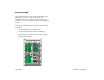
My Working and Certified directories are different. Can I force a reboot from the Working directory? Working and Certified Are Different If the software in the /flash/working directory differs even slightly from the software in the /flash/certified directory, the switch will automatically run from the /flash/certified directory Working Directory Working and Certified contents are different. Working Directory revised_boot.cfg Fbase.img Frelease.img Etc. Certified Directory boot.cfg Fbase.img Frelease.
Loading Software The following section describes the procedure for loading new release software to your switch. Note that the procedure varies slightly for non-redundant (single CMM) and redundant (dual CMM) configurations. Follow the steps that apply to your system. 3 Using your FTP client or the CLI’s rm command, delete all .img files from the /flash/working directory. You can use the asterisk (*) wildcard to delete all .img files at once. For example: -> rm working/*.img Note.
5 Use the install command after the software files have been transferred to the switch via FTP. For example: Redundant Configurations 1 Verify that the OK1 LED is solid green and the OK2 -> install /flash/working/*.img Note. For more information on the install command, refer to the Switch Management Guide or the CLI Reference Guide. LED is flashing green on both the primary and secondary CMM modules.
5 Using your FTP client, upload all required .img files from the new software release to the primary CMM’s /flash/working directory. 6 Use the install command after the software files have been transferred to the switch via FTP. For example: -> install /flash/working/*.img Note. For more information on the install command, refer to the Switch Management Guide or the CLI Reference Guide. 7 Reload the switch from the /flash/working directory.
Using WebView The switch can be configured and monitored using WebView, Alcatel’s Web-based device management tool. WebView software is pre-installed in the switch; you are not required to load additional software. Required Image Files In order to access WebView, the following image files must be present in the current running directory: • Fweb.img Note. Although WebView software is pre-installed, you must first enable HTTP sessions for your switch before you can log in.
Logging In to WebView Note. Before attempting to establish a WebView session, be sure that you have first unlocked the HTTP session type via the aaa authentication command. Otherwise, a login error will occur. See “Unlocking Session Types” on page 22 for more information. Remember, if you have already changed the user name and password for your switch, be sure to use the new information. If you have not changed your user name or password, the factory defaults are admin and switch, respectively.
Navigate the application by clicking on the “Configuration Group” buttons in the left-hand toolbar Refine your navigation by selecting “Configuration Options” for each group from the items displayed in the grey, horizontal navigation bar: “Configuration Options” Toolbar. (In this case, the option “Device” has been selected.) Main “Configuration Group” Toolbar. (In this case, the group “Health” has been selected.) 46 Using WebView Site Maps. WebView also provides site maps for each configuration group.
Online Help Troubleshooting General online help is available through the main Help link located in the top WebView banner: The WebView login screen does not display. This suggests either a physical or network connection issue. Try the following options: • Be sure that you have a good physical Ethernet cable connection to the Ethernet port used for managing the switch (EMP or NI port). • Be sure your computer has a valid Ethernet connection and IP address.
Hardware Basics Chassis Slot Numbering The term “slot” refers to the position at which a module is installed in the chassis. CMM slot positions are designated as Slots A and B. For the OS7700, NI slot numbers range from 1 to 8. For the OS7800, NI slot numbers range from 1 to 16. Power supply bays are also given specific slot numbers. For the OS7700, slot numbers are designated PS-1 through PS-3, from top to bottom. For the OS7800, slot numbers are designated PS-1 through PS-4, from top to bottom.
Chassis Management Module (CMM) The Chassis Management Module (CMM) is the management unit for OmniSwitch 7700/7800 switches. In its role as the management unit, the CMM provides key system services, including: • Console, modem, and Ethernet management port connections to the switch • Software and configuration management, including the Command Line Interface (CLI) • Web-based management (WebView) CMM Redundancy CMM redundancy is an important resiliency feature.
CMM Slot Locations CMM Slot A CMM Slot B CMM Slot A CMM Slot B OmniSwitch 7700 50 Hardware Basics OmniSwitch 7800 March 2005
CMM Front Panel OS7700-CMM Module Status LEDs OK1. Hardware Status. Displays solid green when powered on and the CMM has passed hardware diagnostic tests. Displays solid amber when powered on and the CMM has failed hardware diagnostic tests. OK2. Software Status. Blinks green when the CMM is operational. Displays solid amber when a system software failure occurs. Blinks amber when the software is in a transitional state (e.g., when software is being downloaded to the switch). Module Redundancy LEDs PRI.
Network Interface (NI) Modules The following section outlines front panel information for Network Interface (NI) modules, including LED and port descriptions. For detailed information on all modules, refer to your Hardware Users Guide. ENI Modules Ethernet Network Interface (ENI) modules provide Ethernet connectivity and are available in the following port configurations: • OS7-ENI-C24. Provides 24 twisted-pair ports, auto- negotiating and individually configurable as 10BaseT or 100BaseTX.
Gigabit Interface Converters (GBICs) The OS7-GNI-U2 module provides two Gigabit Interface Converters (GBIC) slots. A GBIC is a Gigabit Ethernet port module that is hot-pluggable—i.e., it can be installed or removed while the GNI is powered on and operating without the risk of damage to the GBIC module or the host circuitry. When a GBIC is installed, the switch automatically gathers basic GBIC information via the connector’s serial E2PROM interface.
OS7-ENI-C24 Front Panel 1x 3x 5x 7x 9x 11x 13x 16x 15x 18x 17x 20x 19x 22x 21x Ethernet Ports The OS7-ENI-C24 module provides 24 Ethernet ports. These ports are twisted-pair and are individually configurable as 10BaseT or 100BaseTX. The ports use RJ45 connectors. 23x Hardware Basics 14x 54 12x Ethernet Port 10x LED Location 8x Refer to the illustration below for the LED locations on each Ethernet port. OK2 6x Ethernet Port LEDs Each Ethernet port has a built-in corresponding LED.
OS7-ENI-FM12 Front Panel OK2. Software Status. Blinks green when the ENI is operational and has successfully loaded software. Displays solid amber when powered on and the ENI has failed to load software. Ethernet Port LEDs Each fiber-based Ethernet port has a corresponding LED. This LED indicates the link and activity status for each Ethernet port. The LED displays green when a valid Ethernet cable connection exists. Flashes green as data is transmitted or received on the port.
OS7-ENI-P24 Front Panel OS7-ENI-P24 OK1. Hardware Status. Displays solid green when powered on and the ENI has passed hardware diagnostic tests. Displays solid amber when powered on and the ENI has failed hardware diagnostic tests. OK1 OK2 1x Module Status LEDs 2x 3x 5x OK2. Software Status. Blinks green when the ENI is operational and has successfully loaded software. Displays solid amber when powered on and the ENI has failed to load software.
OS7-GNI-U2 Front Panel OK2. Software Status. Blinks green when the GNI is operational and has successfully loaded software. Displays solid amber when powered on and the GNI has failed to load software. OS7-GNI-U2 Module Status LEDs OK1. Hardware Status. Displays solid green when powered on and the GNI has passed hardware diagnostic tests. Displays solid amber when powered on and the GNI has failed hardware diagnostic tests.
OS7-GNI-U12 Front Panel OK2. Software Status. Blinks green when the GNI is operational and has successfully loaded software. Displays solid amber when powered on and the GNI has failed to load software. OS7-GNI-U12 Module Status LEDs OK1. Hardware Status. Displays solid green when powered on and the GNI has passed hardware diagnostic tests. Displays solid amber when powered on and the GNI has failed hardware diagnostic tests.
OS7-GNI-C12 Front Panel OK2. Software Status. Blinks green when the GNI is operational and has successfully loaded software. Displays solid amber when powered on and the GNI has failed to load software. Ethernet Port LEDs Each Gigabit Ethernet port has two built-in corresponding LEDs. The top LED indicates 10/100 Mbps link and activity status for the port while the bottom LED indicates 1 Gigabit link and activity status for the port.
The CD that accompanies this Getting Started Guide contains comprehensive Alcatel user documentation, including the following manuals: • OmniSwitch 7700/7800 Getting Started Guide Describes the hardware and software procedures for getting an OmniSwitch 7700/78000 up and running. Also provides information on fundamental aspects of OmniSwitch hardware components and software architecture.
User Documentation on CD March 2005 User Documentation on CD 61
• OmniSwitch 7700/7800/8800 Advanced Routing Configuration Guide Includes network configuration procedures and descriptive information on all the software features and protocols included in the advanced routing software package. Chapters cover multicast routing (DVMRP and PIM-SM) and OSPF. General Information If you cannot locate a button with the document image behind the binoculars (as shown), then the global search feature is not available in the version of Acrobat Reader you are currently using.