
User Guide
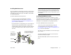
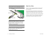
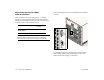
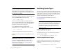
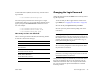
Table Of Contents
- (START page)
- Home
- Front Matter
- Table of Contents
- OmniSwitch 7700/7800
- Installing the Hardware
- Connections and Cabling
- Booting the Switch
- Your First Login Session
- CLI Basics
- Files and Directories
- Loading Software
- Using WebView
- Hardware Basics
- User Documentation on CD
March 2005 Installing the Hardware 15
Installing GBIC Connectors
If you are installing an OS7-GNI-U2 module, you must install
Gigabit Interface Converters (GBICs) as required. OS7-GNI-
U2 modules provide ports for up to two GBICs. These GBICs
are packaged separately.
To install a GBIC follow the steps below.
1 Be sure you have eliminated ESD by using the
provided grounding wrist strap. Refer to “Using the
Grounding Wrist Strap and Chassis Grounding Lug” on
page 12 for more information.
2 Note that there is an alignment groove used to keep the
GBIC from being installed backwards or upside-down.
Orient the GBIC with the slot located on the OS7-GNI-U2
module and carefully slide the GBIC into place until the
tabs lock.
Caution. Do not force the GBIC into the slot. If the GBIC
does not slide easily into position, verify that the GBIC
grooves are aligned properly. Forcing the GBIC into the
slot can damage the unit, as well as components on your
GNI module.
Installing MiniGBIC Connectors
If you are installing an OS7-GNI-U12 module, you must
install Miniature Gigabit Interface Converters (MiniGBICs) as
required. OS7-GNI-U12 modules provide ports for up to 12
MiniGBICs. These MiniGBICs are packaged separately.
To install a MiniGBIC follow the steps below.
1 Be sure you have eliminated ESD by using the
provided grounding wrist strap. Refer to “Using the
Grounding Wrist Strap and Chassis Grounding Lug” on
page 12 for more information.
2 When inserting a MiniGBIC, be sure that the hinged
face is closed.
3 Slide the MiniGBIC straight into the slot until the
module clicks firmly into place.
4 Push the MiniGBIC into the slot until it clicks into
place.
To remove the GBIC, press
and hold tabs while sliding
the module out of the slot.
To install the
GBIC, insert the
module firmly
into the slot until
the tabs click.
Press tab
Press tab
GBIC Module
Groove
GBIC Slot
GNI Module