
User Guide
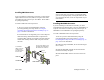
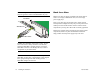
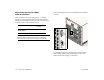
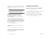
Table Of Contents
- (START page)
- Home
- Front Matter
- Table of Contents
- OmniSwitch 7700/7800
- Installing the Hardware
- Connections and Cabling
- Booting the Switch
- Your First Login Session
- CLI Basics
- Files and Directories
- Loading Software
- Using WebView
- Hardware Basics
- User Documentation on CD

March 2005 Connections and Cabling 17
Once your switch is properly installed, you should connect all
network and management cables required for your network
applications. Connections may include:
• Serial cable to the console port
• Ethernet cable to the Ethernet Management Port (EMP)
on the CMM
• Gigabit cables to all required GBICs or MiniGBICs
• Ethernet cables to all required Ethernet Network
Interface (ENI) ports
Serial Connection to the Console/Modem Port
The console port, located on the CMM module, provides a
serial connection to the switch and is required when logging
into the switch for the first time. By default, this female DB-9
connector provides a DCE console connection. However, by
changing the onboard jumper setting, the port can be changed
to a DTE modem connection.
Modem Connections. If you require a modem connec-
tion to the switch, you must convert the console port to
support modem connections by installing a hardware
jumper on the CMM. Refer to your Hardware Users
Guide for details.
Serial Connection Default Settings
The factory default settings for the serial connection are as
follows:
For information on modifying these settings, refer to
“Modifying the Serial Connection Settings” on page 26.
Connections and Cabling
baud rate 9600
parity none
data bits (word size) 8
stop bits 1