
User Guide
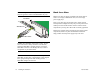
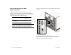
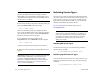
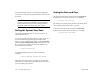
Table Of Contents
- (START page)
- Home
- Front Matter
- Table of Contents
- OmniSwitch 7700/7800
- Installing the Hardware
- Connections and Cabling
- Booting the Switch
- Your First Login Session
- CLI Basics
- Files and Directories
- Loading Software
- Using WebView
- Hardware Basics
- User Documentation on CD

March 2005 Booting the Switch 19
Now that you have installed the switch components and
connected all required cables, you can boot the switch. To boot
the switch, simply turn the on/off switch for all installed power
supplies to the on ( | ) position.
Note. If you have more than one power supply installed,
be sure to turn on each power supply in rapid succession,
(i.e., within a few seconds of each other). This ensures that
there will be adequate power for all NI modules when they
boot.
Component LEDs
The boot process takes a few moments to complete. During
this process, the LEDs on the CMM and NI modules may flash
and change color, indicating different stages of the boot.
Following a successful boot, the LEDs on all switch compo-
nents, including power supplies, should display as follows:
If the LEDs do not display as indicated, make sure the boot
process is completed. Again, the boot process takes several
moments to complete. If the LEDs do not display as indicated
following a complete boot sequence, contact Alcatel Customer
Support.
For descriptions of CMM and NI LED states, see pages 51
through 59. For information on power supply LED states, refer
to the Hardware Users Guide.
Once the switch has completely booted and you have accessed
your computer’s terminal emulation software via the console
port, you are ready to log in to the switch’s Command Line
Interface (CLI) and configure basic information. Continue to
“Your First Login Session” on page 20.
Booting the Switch
CMM OK1 Solid Green
CMM OK2 Blinking Green
CMM TEMP Solid Green
CMM FAN Solid Green
NI OK1 Solid Green
NI OK2 Blinking Green
Power Supply AC OK Solid Green
Power Supply DC OK Solid Green
Power Supply OVER TEMP Off