
User Guide

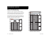
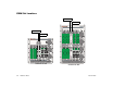
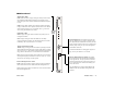
Table Of Contents
- (START page)
- Home
- Front Matter
- Table of Contents
- OmniSwitch 7700/7800
- Installing the Hardware
- Connections and Cabling
- Booting the Switch
- Your First Login Session
- CLI Basics
- Files and Directories
- Loading Software
- Using WebView
- Hardware Basics
- User Documentation on CD
54 Hardware Basics March 2005
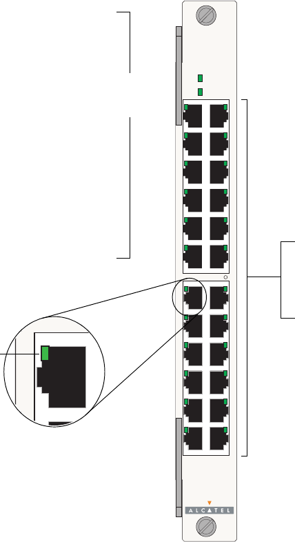
OS7-ENI-C24 Front Panel
OS7-ENI-C24
1x 3x 5x 7x 9x 11x 13x 15x 17x 19x 21x 23x
OK1
OK2
22x20x18x16x14x12x10x8x6x4x
Module Status LEDs
OK1. Hardware Status. Displays solid green when powered
on and the ENI has passed hardware diagnostic tests. Dis-
plays solid amber when powered on and the ENI has failed
hardware diagnostic tests.
OK2. Software Status. Blinks green when the ENI is opera-
tional and has successfully loaded software. Displays solid
amber when powered on and the ENI has failed to load soft-
ware.
Ethernet Port LEDs
Each Ethernet port has a built-in corresponding LED. This
LED indicates the link and activity status for each Ethernet
port. The LED displays green when a valid Ethernet cable
connection exists. Flashes green as data is transmitted or
received on the port.
Refer to the illustration below for the LED locations on each
Ethernet port.
Ethernet Ports
The OS7-ENI-C24 module provides 24 Ethernet ports.
These ports are twisted-pair and are individually con-
figurable as 10BaseT or 100BaseTX. The ports use RJ-
45 connectors.
Ethernet Port
LED Location
Module
Status
LEDs