Part No. 060334-10, Rev. G December 2013 OmniSwitch 6900 Hardware Users Guide www.alcatel-lucent.
This user guide documents the OmniSwitch 6900 for AOS Release 7.3.3. This user guide documents OmniSwitch 6900 hardware, including chassis and associated components. The specifications described in this guide are subject to change without notice. Copyright© 2013 by Alcatel-Lucent. All rights reserved. This document may not be reproduced in whole or in part without the express written permission of Alcatel-Lucent.
Contents About This Guide ......................................................................................................... vii Supported Platforms ......................................................................................................... vii Who Should Read this Manual? ....................................................................................... vii When Should I Read this Manual? ...................................................................................
Contents OmniSwitch 6900 Expansion Modules .........................................................................2-11 OS-XNI-U4 ............................................................................................................2-11 OS-XNI-U12 ..........................................................................................................2-11 OS-QNI-U3 ............................................................................................................2-12 OS-HNI-U6 ............
Contents Appendix A Regulatory Compliance and Safety Information .............................................. A-1 Declaration of Conformity: CE Mark ............................................................................ A-1 Waste Electrical and Electronic Equipment (WEEE) Statement ............................ A-1 China RoHS: Hazardous Substance Table ..................................................................... A-2 Standards Compliance ....................................................
Contents vi OmniSwitch 6900 Hardware Users Guide December 2013
About This Guide This OmniSwitch 6900 Hardware Users Guide describes OmniSwitch 6900 switch components and basic switch hardware procedures. Supported Platforms The information in this guide applies only to OmniSwitch 6900 switches. Who Should Read this Manual? The audience for this users guide is network administrators and IT support personnel who need to configure, maintain, and monitor switches and routers in a live network.
What is in this Manual? This users guide includes the following hardware-related information: • Descriptions of “Availability” features. • Technical specifications for the chassis, power supplies, modules and fan tray. • Power supply requirements. • The dynamics of chassis airflow, including detailed illustrations of proper and improper airflow configurations. • Hot-swapping power supplies, fan trays and modules. • Installation and removal procedures for power supplies, fan trays and modules.
Documentation Roadmap The OmniSwitch user documentation suite was designed to supply you with information at several critical junctures of the configuration process.The following section outlines a roadmap of the manuals that will help you at each stage of the configuration process. Under each stage, we point you to the manual or manuals that will be most helpful to you.
Anytime The OmniSwitch CLI Reference Guide contains comprehensive information on all CLI commands supported by the switch. This guide includes syntax, default, usage, example, related CLI command, and CLI-to-MIB variable mapping information for all CLI commands supported by the switch. This guide can be consulted anytime during the configuration process to find detailed and specific information on each CLI command.
Related Documentation The following are the titles and descriptions of all the OmniSwitch 6900 user manuals: • OmniSwitch 6900 Getting Started Guide Describes the hardware and software procedures for getting an OmniSwitch up and running. Also provides information on fundamental aspects of OmniSwitch software architecture. • OmniSwitch 6900 Hardware Users Guide Complete technical specifications and procedures for all OmniSwitch 6900 chassis, power supplies, fans, and Network Interface (NI) modules.
Technical Support An Alcatel-Lucent service agreement brings your company the assurance of 7x24 no-excuses technical support. You’ll also receive regular software updates to maintain and maximize your Alcatel-Lucent product’s features and functionality and on-site hardware replacement through our global network of highly qualified service delivery partners.
1 OmniSwitch 6900 The OmniSwitch 6900 (OS6900) is a family of standalone aggregation switches that can also be installed as top-of-rack boxes in data centers. The OS6900 supports either 20 or 40 non-combo SFP+ or 10GBase-T ports, as well as expansion modules. Refer to the information below for model number and component type.
OmniSwitch 6900 OmniSwitch 6900-X20 OmniSwitch 6900-X40 OmniSwitch 6900-T20 OmniSwitch 6900-T40 page 1-2 OmniSwitch 6900 Hardware Users Guide December 2013
OmniSwitch 6900 OmniSwitch 6900 Availability Features OmniSwitch 6900 Availability Features The switch provides a broad variety of availability features. Availability features are hardware and software-based safeguards that help prevent the loss of data flow in the unlikely event of a subsystem failure. In addition, some availability features allow users to maintain or replace hardware components without powering off the switch or interrupting switch operations.
OmniSwitch 6900 Availability Features OmniSwitch 6900 Hardware Monitoring Automatic Monitoring Automatic monitoring refers to the switch’s built-in sensors that automatically monitor operations. If an error is detected (e.g., over-threshold temperature), the switch immediately sends a trap to the user. The trap is displayed on the console in the form of a text error message. LEDs LEDs, which provide visual status information, are provided on the front and rear panels.
2 Chassis and Power Supplies This chapter includes detailed information on the OmniSwitch 6900 chassis, as well as fan tray and power supply components. Topics include: • Technical specifications, page 2-4 and page 2-8. • Switch mounting information, page 2-15. • Power supplies and power supply redundancy, page 2-27. • Temperature management, page 2-38. • Chassis fan tray on page 2-39.
OmniSwitch 6900 Chassis Chassis and Power Supplies OmniSwitch 6900 Chassis A B C OS6900-X20 OS6900-X20 Front Panel E M P E M P U S B E U S B CONSOLE 1 OK 2 3 4 5 6 7 8 9 10 11 12 F 13 14 15 16 17 18 19 20 PS EMP D Item Description A Ethernet Management Port (EMP) B USB Port C Console Port D Status LEDs E 20 Non-Combo 10G Ethernet Ports F Expansion Module Slot F A R B C PS1 Item Description A Chassis Grounding Lug B Fan Tray C Power Supply Bays (OS6900-BP-
Chassis and Power Supplies OmniSwitch 6900 Chassis A B C OS6900-X40 OS6900-X40 Front Panel E M P E M P U S B E U S B CONSOLE 1 OK 2 3 4 5 6 7 8 9 10 11 12 15 16 13 14 17 18 PS EMP 19 20 21 22 F 23 24 25 26 27 28 29 30 31 32 33 34 35 36 37 38 39 40 D Item Description A Ethernet Management Port (EMP) B USB Port C Console Port D Status LEDs E 40 Non-Combo 10G Ethernet Ports F Expansion Module Slot F A B R C SLOT 3 Item Description A Chassis Grounding
OmniSwitch 6900 Chassis Chassis and Power Supplies OS6900-X20 and OS6900-X40 Chassis Specifications Note. For OS6900-T20 and OS6900-T40 chassis specifications, please refer to page page 2-8. Chassis Width (with brackets) Chassis Width (without brackets) 48.2 cm (19 inches) 43.3 cm (17.05 inches) Chassis Height 4.4 cm (1.73 inches or 1RU) Overall Chassis Depth 55.9 cm (22 inches) OS6900-X20 Chassis Weight (w/factory-installed fan tray only) 7.61 kg (16.
Chassis and Power Supplies OmniSwitch 6900 Chassis *Note On Chassis Versus Ambient Temperatures. Chassis temperature refers to the sensor reading of the internal switch temperature (threshold or danger). Ambient temperature refers to the approximate room temperature. The ambient temperature will typically be lower than the chassis temperature. Due to different airflow characteristics, chassis temperatures will vary by model.
OmniSwitch 6900 Chassis Chassis and Power Supplies OS6900-T20 Front Panel A E D C B Item Description A USB Port B Console Port C Status LEDs D 20 Non-Combo 10GBase-T Ports E Expansion Module Slot OS6900-T20 Rear Panel A C B Item Description A Ethernet Management Port (EMP) B Chassis Grounding Lug C Fan Tray D Power Supply Bays page 2-6 OmniSwitch 6900 Hardware Users Guide D December 2013
Chassis and Power Supplies OmniSwitch 6900 Chassis OS6900-T40 Front Panel A E D C B Item Description A USB Port B Console Port C Status LEDs D 40 Non-Combo 10GBase-T Ports E Expansion Module Slot OS6900-T40 Rear Panel A D C E B Item Description A Ethernet Management Port (EMP) B Chassis Grounding Lug C Expansion Module Slot D Fan Tray E Power Supply Bays OmniSwitch 6900 Hardware Users Guide December 2013 page 2-7
OmniSwitch 6900 Chassis Chassis and Power Supplies OS6900-T20 and OS6900-T40 Chassis Specifications Note. For OS6900-X20 and OS6900-X40 chassis specifications, please refer to page page 2-4. Chassis Width (with brackets) Chassis Width (without brackets) 48.2 cm (19 inches) 43.3 cm (17.05 inches) Chassis Height 4.4 cm (1.73 inches or 1RU) Overall Chassis Depth 55.9 cm (22 inches) OS6900-T20 Chassis Weight (w/factory-installed fan tray only) 7.61 kg (16.
Chassis and Power Supplies OmniSwitch 6900 Chassis *Note On Chassis Versus Ambient Temperatures. Chassis temperature refers to the sensor reading of the internal switch temperature (threshold or danger). Ambient temperature refers to the approximate room temperature. The ambient temperature will typically be lower than the chassis temperature. Due to different airflow characteristics, chassis temperatures will vary by model. Note.
OmniSwitch 6900 Chassis Chassis and Power Supplies Port Speeds Supported Model Port Type Port Speeds OS6900-X20 SFP+ 1G/10G OS6900-X40 SFP+ 1G/10G OS-XNI-U4 Expansion Module SFP+ 1G/10G OS-XNI-U12 Expansion Module SFP+ 1G/10G OS-XNI-U12E Expansion Module SFP+ Fibre Channel 1G/10G 2G/4G/8G OS6900-T20 10GBase-T 100Mbps/1G/10G OS6900-T40 10GBase-T 100Mbps/1G/10G OS-XNI-T8 Expansion Module 10GBase-T 100Mbps/1G/10G Chassis Status LEDs The chassis provides a series of status LEDs loca
Chassis and Power Supplies OmniSwitch 6900 Expansion Modules OmniSwitch 6900 Expansion Modules OS-XNI-U4 A OS-XNI-U4 CLASS 1 LASER PRODUCT 1 3 B 2 4 1 C 3 2 4 Item Description A Lock Lever and Captive Screw B SFP+ Ports C Status LEDs Power Consumption 19W (fully populated) OS-XNI-U12 A OS-XNI-U12 CLASS 1 LASER PRODUCT 1 11 B 2 C 12 1 2 3 4 5 6 7 8 9 Item Description A Lock Lever and Captive Screw B SFP+ Ports C Status LEDs Power Consumption 44W (fully populate
OmniSwitch 6900 Expansion Modules Chassis and Power Supplies OS-QNI-U3 A B C Item Description A Lock Lever and Captive Screw B QSFP+ Ports C Status LEDs Power Consumption 34W (fully populated) OS-HNI-U6 A B D C Item Description A Lock Lever and Captive Screw B SFP+ Ports C Status LEDs D QSFP+ Ports Power Consumption 37W (fully populated) CAUTION - TRANSCEIVERS ARE CLASS 1M LASER RADIATION WHEN OPEN. DO NOT VIEW DIRECTLY WITH OPTICAL INSTRUMENTS.
Chassis and Power Supplies OmniSwitch 6900 Expansion Modules OS-XNI-T8 A B C Item Description A Lock Lever and Captive Screw B 10GBase-T Ports C Status LEDs Power Consumption 54W Cable Supported Cat 5e; Cat 6; Cat 6a; Cat 7 Cable Distances 55 meters Cat 5e and Cat 6 100 meters Cat 6a and Cat 7 Note. OS-XNI-T8 modules do not support Category 5 (Cat 5) cable.
OmniSwitch 6900 Expansion Modules Chassis and Power Supplies OS-XNI-U12E A CLASS 1 LASER PRODUCT 11 1 B 2 C 12 1 2 3 4 5 6 7 8 9 Item Description A Lock Lever and Captive Screw B SFP+/FC Ports C Status LEDs Power Consumption 31W (max. power, fully populated) 10 11 12 Note. OS-XNI-U12E modules support 12X10G SFP+ or 12X2G/4G/8G Fibre Channel connections. An Alcatel-Lucent Data Center License is required for Fibre Channel operation.
Chassis and Power Supplies Mounting the Switch Mounting the Switch General Mounting Recommendations Elevated Operating Ambient Temperature. If installed in a closed or multi-rack assembly, the operating ambient temperature of the rack environment may be greater than the room’s ambient temperature. Therefore, consideration should be given to the maximum rated ambient temperature (Tmra) specified on page 2-4 (OS6900-X20 and OS6900-X40) and page 2-8 (OS6900-T20 and OS6900-T40). Reduced Air Flow.
Mounting the Switch Chassis and Power Supplies Airflow Recommendations To ensure proper airflow, be sure that your switch is placed in a well-ventilated area and provide minimum recommended clearance at the front, back and sides of the switch, as shown below. Restricted airflow can cause your switch to overheat, which can lead to switch failure.
Chassis and Power Supplies Mounting the Switch Front-to-Rear Airflow The OmniSwitch 6900 fan tray and power supplies are located at the rear of the switch and draw air through the intake vents located at the top-front of the chassis. The air is directed straight through the chassis’ module compartment and past the switch’s circuit boards. Airflow is then exhausted through their vents.
Mounting the Switch Chassis and Power Supplies Blank Cover Panels Blank cover panels are provided with your switch and are used to cover empty slots. These cover panels play an important role in chassis airflow and temperature management. If your switch is not fully populated and blank cover panels are not installed over empty slot locations, airflow is affected.
Chassis and Power Supplies Rack-Mounting Rack-Mounting Refer to the following important guidelines before installing the chassis in a rack: • Two people are required to rack mount the switch: One person to lift the chassis into position and one person to secure the chassis to the rack using the rack mount screws. • The chassis has rack-mount flanges that support standard 19-inch rack mount installations. • Alcatel-Lucent does not provide rack-mount screws. Use the screws supplied by the rack vendor.
Rack-Mounting Chassis and Power Supplies 5 Once the holes are aligned, the second person should insert a screw through the bottom hole on each flange. Tighten both screws until they are secure. Chassis Front 6 From the back of the chassis and with the flanges facing out, insert the slide-in braces into the slot rails until they meet the rack posts. Chassis Rear 7 The chassis installation should be level.
Chassis and Power Supplies Rack-Mounting Mid-Mounting the Chassis In the Rack The switch may also be installed in the rack using mid-mount flanges. To mid-mount the switch in a rack, follow the steps below. 1 If needed, remove the mounting flanges from the front of the chassis and the slot rails from the side of the chassis by unscrewing the attachment screws. 2 Reinstall the mounting flanges at the mid point of the chassis using the threaded holes, as shown in the diagram below.
Rack-Mounting Chassis and Power Supplies 6 Once the holes are aligned, the second person should insert a screw through the bottom hole on each flange. Tighten both screws until they are secure. 7 Once the flanges are aligned, install the remaining screws. Be sure that all screws are securely tightened.
Chassis and Power Supplies Rack-Mounting Standalone (Non-Rack Mounted) Installations The chassis can also be placed unmounted on a stable, flat surface as a standalone unit. Be sure that the surface can accommodate the full, populated weight of all switches being installed. Approximate chassis weights are provided on page 2-4 (OS6900-X20 and OS6900-X40) and page 2-8 (OS6900-T20 and OS6900-T40).
Plug-In Modules Chassis and Power Supplies Plug-In Modules Hot-Swapping Plug-In Modules Hot-swapping guidelines apply to the various plug-in modules. In some cases a reboot is required. Refer to the table below for the supported hot-swap scenarios for each plug-in module.
Chassis and Power Supplies Plug-In Modules Installing Plug-In Modules Note. When installing plug-in modules, the transceivers must not be installed. Otherwise, the transceivers will interfere with the module’s lock lever. 1 With the lock lever in the open position, insert the module into the chassis card guides and slide the module straight back. 2 When the bottom portion of the lever meets the chassis, be sure that the catches grab the chassis sheet metal, then push the lever up and back as shown.
Plug-In Modules Chassis and Power Supplies 3 Tighten the captive screw to complete the installation.
Chassis and Power Supplies Plug-In Modules Removing Plug-In Modules 1 Loosen the captive screw. 2 Pull down on the lock lever to release the plug-in module from the chassis backplane. 3 Using the lock lever as a handle, pull the plug-in module straight back and out of the chassis.
Power Supplies Chassis and Power Supplies Power Supplies OmniSwitch 6900 power supplies are located at the rear of the switch chassis. Refer to page 2-2 and page 2-3 for more information on component location. Two slots are provided. If a second power supply is installed, it will assume a standby role. Please note that the OS6900 does not provide an on/off switch. Connecting an installed power supply to a power source will boot the switch.
Chassis and Power Supplies Power Supplies AC Power Supply LED States LED State Description Solid Green The power supply is operating normally and providing power to the chassis Flashing Green The power supply is on standby and can provide power to the chassis if power supply failover should occur Flashing Red No AC power is being provided to this power supply Flashing Green/Red Power supply warning Solid Red Power supply failure Off No AC power is being provided to any power supply installed
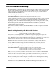
Power Supplies Chassis and Power Supplies DC Power Supply Status LED Lock Tab DC Connector Air Vent Handle DC Power Supply Front Panel Model (OS-PS-450W-D) OS6900-BPD-F (YM-2451D), Front-to-Rear OS6900-BPD-R (YM-2451P), Rear-to-Front (Purple Coloring) Product Compatibility OmniSwitch 6900 Input Voltage Range -36V (min.); -48V (nominal); -72V (max.); -75V (peak) Input Current 14A (40VDC), 9A (60VDC), nominal is 11.5A (48VDC) Output Rating 2A min to 36.
Chassis and Power Supplies Power Supplies DC Power Supply Connections Connecting a DC Cable Harness to the Chassis Power Supply When plugging in the cable, insert the connector end of the cable harness into the power supply connector until it clicks firmly into place. This is an indication that the connector is secure and properly seated.
Power Supplies Chassis and Power Supplies Installing Power Supplies 1 Orient the power supply so that the power cord socket is situated at the right of the power supply. Also, for the power supply to seat properly, make sure that the handle is in the vertical position as shown. Lock Tab 2 Slide the power supply back until it is securely seated in the chassis backplane.When the connector is fully seated, the lock tab will click and hold the power supply in place.
Chassis and Power Supplies Power Supplies Removing Power Supplies 1 When removing a power supply, first disconnect the power cord from the power source. Once the power cord is disconnected, pull the power cord out of the power supply housing. 2 Pressing the lock tab toward the right, as shown, will free the power supply from the chassis. While pressing the lock tab, pull the power supply straight back and out of the chassis slot. Lock Tab Note.
Chassis Fan Tray Chassis and Power Supplies Chassis Fan Tray The OmniSwitch 6900 chassis houses a single fan tray with four independently-operating fan. The fans are the main temperature control components for the switch, providing cooling airflow for all chassis components. This airflow is a crucial factor in the switch’s overall operability. Refer to “Airflow Recommendations” on page 2-16 for more information. Important. The fan tray is a required component.
Chassis and Power Supplies Removing the Fan Tray Removing the Fan Tray 1 Begin by loosening the two captive screws located at the left and right sides of the tray’s front panel. 2 Pull the fan tray straight out of the chassis. Important. The switch should not run without a fan tray more than 60 seconds to prevent over heating.
Removing the Fan Tray Chassis and Power Supplies Installing the Fan Tray 1 Insert the tray into the chassis slot and slide it straight back until it meets the chassis backplane connectors. 2 When the fan tray is firmly seated in the chassis, tighten the two captive screws at the left and right sides of the fan tray’s front panel.
Chassis and Power Supplies Grounding the Chassis Grounding the Chassis The switch has a grounding lug located on the rear of the chassis. This lug uses 10-32 screws and is surrounded by a small paint-free area, which provides metal-to-metal contact for a ground connection. Use this connector to supplement the ground provided by the AC power cord. To do so, install a Panduit Grounding Lug (type LCD8-10A-L) using 8AWG copper conductors to the paint-free area.
Monitoring Chassis Components Chassis and Power Supplies Monitoring Chassis Components Viewing Chassis Slot Information To view basic slot information, enter the show module command at the CLI prompt: -> show module To view more detailed information, use the show module long command: -> show module long Monitoring Chassis Temperature The operating temperature of your switch is a critical factor in its overall operability.
Chassis and Power Supplies Monitoring Chassis Temperature Temperature Errors The switch monitors the ambient air temperature at all times via an onboard sensor. If an over-temperature condition occurs, there are two different levels of error severity: • Warning threshold has been exceeded • Danger threshold has been exceeded Warning Threshold If the temperature exceeds the switch’s user-configurable warning threshold, the switch sends out a trap.
Monitoring Chassis Temperature page 2-40 Chassis and Power Supplies OmniSwitch 6900 Hardware Users Guide December 2013
A Regulatory Compliance and Safety Information This appendix provides information on regulatory agency compliance and safety for OmniSwitch 6900 switches. Declaration of Conformity: CE Mark This equipment is in compliance with the essential requirements and other provisions of Directive 2004/108/EC (EMC), 2006/95/EC (LVD), 91/263/EEC (Telecom Terminal Equipment, if applicable), 1999/5/EC (R&TTE, if applicable).
China RoHS: Hazardous Substance Table Regulatory Compliance and Safety Information China RoHS: Hazardous Substance Table 产品说明书附件 SUPPLEMENT TO PRODUCT INSTRUCTIONS 这个文件涉及的是在中华人民共和国境内进口或销售的电子信息产品 Include this document with all Electronic Information Products imported or sold in the People’s Republic of China 部件名称 (Parts) 电路模块 (Circuit Modules) 电缆及电缆组件 (Cables & Cable Assemblies) 金属部件 (Metal Parts) 塑料和聚合物部件 (Plastic and Polymeric parts) 铅 ( Pb) 有毒有害物质或元素 (Hazardous Substance) 汞 镉 六价铬 多溴联苯 6+ ( Hg) ( C
Regulatory Compliance and Safety Information China RoHS: Hazardous Substance Table Products are packaged using one or more of the following packaging materials: CB Corrugated Cardboard OmniSwitch 6900 Hardware Users Guide FB Corrugated Fiberboard December 2013 Low-Density Polyethylene page A-3
Standards Compliance Regulatory Compliance and Safety Information Standards Compliance The product bears the CE mark. In addition it is in compliance with the following other safety and EMC standards: All hardware switching modules used in an OmniSwitch 6900 switch comply with Class A standards. Modules with copper connectors meet Class A requirements using unshielded (UTP) cables. Safety Standards • UL 60950-1, 2nd Edition • CAN/CSA-C22.2 No.
Regulatory Compliance and Safety Information Standards Compliance Environmental Standards • ETS 300 019 Storage Class 1.1 • ETS 300 019 Transportation Class 2.3 • ETS 300 019 Stationary Use Class 3.1 FCC Class A, Part 15 This equipment has been tested and found to comply with the limits for Class A digital device pursuant to Part 15 of the FCC Rules.These limits are designed to provide reasonable protection against harmful interference when the equipment is operated in a commercial environment.
Standards Compliance Regulatory Compliance and Safety Information CISPR22 Class A warning This is a Class A product. In a domestic environment, this product may cause radio interference. Under such circumstances, the user may be requested to take appropriate countermeasures. VCCI This is a Class A product based on the standard of the Voluntary Control Council for Interference by Information Technology Equipment (VCCI). If this equipment is used in a domestic environment, radio disturbance may arise.
Regulatory Compliance and Safety Information Translated Safety Warnings Translated Safety Warnings Blank Panels Warning Because they regulate airflow and help protect internal chassis components, blank cover plates should remain installed at empty module slots and power supply bays at all times.
Translated Safety Warnings Regulatory Compliance and Safety Information Invisible Laser Radiation Warning Lasers emit invisible radiation from the aperture opening when no fiber-optic cable is connected. When removing cables do not stare into the open apertures. In addition, install protective aperture covers to fiber ports with no cable connected.
Regulatory Compliance and Safety Information DC Power Supply Connection Warning Proper Earthing Requirement Warning To avoid shock hazard: • The power cord must be connected to a properly wired and earth receptacle. • Any equipment to which this product will attached must also be connected to properly wired receptacles. Français: Pour éviter tout risque de choc électrique: • Ne jamais rendre inopérant le conducteur de masse ni utiliser l'équipement sans un conducteur de masse adéquatement installé.
DC Power Supply Connection Warning Regulatory Compliance and Safety Information Read Important Safety Information Warning The Getting Started Guide that accompanied this equipment contains important safety information about which you should be aware when working with hardware components in this system. You should read this guide before installing, using, or servicing this equipment.
Regulatory Compliance and Safety Information Instrucciones de seguridad en español Instrucciones de seguridad en español Advertencia sobre el levantamiento del chasis Se requieren dos personas para levantar el chasis. Debido a su peso, la elevación del chasis sin ayuda puede causar daños corporales. También es seguro doblar sus rodillas y guardar su espalda derecho al ayudar a levantar el chasis.
Instrucciones de seguridad en español Regulatory Compliance and Safety Information Advertencia sobre una apropiada conexión a tierra Para evitar peligro de descargas: • El cable de alimentación debe estar conectado a una toma de alimentación adecuadamente cableada y con toma de tierra. Cualquier equipo al cual se conecte este producto debe estar también conectado a tomas de alimentación adecuadamente cableadas.