MDR-8000/i/s/u Microwave Digital Radios Users Manual Alcatel Part Number 3EM15726AA Issue 2, June, 2004 Part 2 of 2 3400 West Plano Parkway Plano, Texas 75075-5813 U.S.A.
4 INITIAL TURNUP 4.1 SECTION INTRODUCTION This section describes the procedures required to turn up the MDR-8000 Microwave Digital Radios after installation. This provisioning part of the section describes provisioning options available with the MDR-8000 software application. Provisioning allows for the definition, editing, and storing of specific functions. The MDR-8000 provides the ability to provision equipment and facilities through a series of Windows™-based screens and messages.
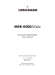
START FIG 4-2 DS1/E1, DS3, OC3 RADIO CONFIG PROVISIONING DS1/E1 DS3 OC3 FIG 4-3 DS1/E1 RADIO CONFIG PROVISIONING FIG 4-5 DS3 RADIO CONFIG PROVISIONING FIG 4-8 OC3 RADIO CONFIG PROVISIONING FIG 4-4 DS1/E1 FACILITIES PROVISIONING FIG 4-6 DS3 FACILITIES PROVISIONING FIG 4-9 OC3 FACILITIES PROVISIONING FIG 4-7 DS3 RADIO WAYSIDE DS1 FACILITIES PROVISIONING FIG 4-10 OC3 RADIO WAYSIDE DS1 FACILITIES PROVISIONING FIG 4-11 DS1/E1, DS3, OC3 RADIO SERVICE CHANNEL PROVISIONING FIG 4-12 DS1/E1, DS3, OC3 RADI
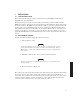
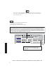
4.3 PROVISIONING RADIO Note Screen shown is for DS1 Radio. DS3 and OC3 radio configuration provisioning is similar. Changes to provisioning do not have to be made in any particular order. Open radio provisioning screens. On main screen, double click on tower icon. Status and alarm screen displays. Click on Provisioning. Check current provisioning and change as required. SELECT TERMINAL, REPEATER, RING TERMINAL OR RING REPEATER FROM DROP DOWN LIST.
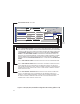
Note Screen shown is for DS1 Radio. DS3 and OC3 radio configuration provisioning is similar. Changes to provisioning do not have to be made in any particular order. NOTES 1. ATPC T/O IS A CMD PATH FUNCTION PERFORMED AT XMTR. 2. ATPC TRACKS RCVR WITH HIGHEST LEVEL. 3. LOW POWER ATPC IS 10dB DOWN FROM HIGH POWER. SELECT ATPC OR ATPC T/O ENABLE AUTOMATIC XMT POWER CONTROL (ATPC) FUNCTION. WHEN PROVISIONED ATPC OR ATPC T/0, ONE RCVR OUT-OF-LOCK CAUSES HIGH POWER ATPC FOR 10 SECONDS EVERY ONE MINUTE.
Note MASTER RING CONFIGURATIONS – Master rings are networks that consist entirely of a loop of synchronous repeaters. All nodes in the same ring direction use the same clock timing. Timing may be different for each direction. All service channel data is passed synchronously around the ring. The status of the ring is monitored using messages in the ELMC channel.
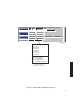
RING TERMINAL MASTER – NOT USED SYSTEM ID: RADIO TYPE: RADIO CONFIG: ELMC: MDR-8000 OC3 HS Tx ATPC Enabled SYSTEM ALARM Visual/Audible RCV SWITCHING: Disable AGC OPTIONS: RADIO LINK ID: TEST1 Option Key: Disable OC-3 128 QAM HS Rx A&B PA Present RELAYS ON/NO BER Disable Ring Repeater Normal Terminal Normal Repeater Primary Ring Terminal Station Alarm 13-16 Ring Repeater Degrade Enable Secondary RSL Alarm Enable Master Stat/Prov/WaySide LMW-9089 09/08/03 SELECT RING TERMINAL NORMAL
SYSTEM ID: RADIO TYPE: RADIO CONFIG: ELMC: TEST1 MDR-8000 DS1 RADIO LINK ID: 16 LINES HS Tx/HS Rx TERMINAL ATPC Enabled A&B PA Present SYSTEM ALARM Visual/Audible RELAYS ON/NO RCV SWITCHING: Disable AGC BER Disable OPTIONS: Option Key: Disable 128 TCM 6-8 GHz Station Alarm 13-16 RSL Alarm Enable Stat/Prov/WaySide LMW-7100-SM 09/16/02 SELECT ONE: * NS Tx/NS Rx NS Tx/HS Rx * NS Tx/SD Rx * HS Tx/HS Rx * HS Tx/SD Rx FD TxA/Rx A FD TxA/Rx B NS = NON-STANDBY HS = HOT-STANDBY SD = SPACE DIVE
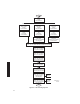
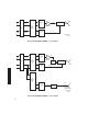
I RPTR CH RPTR CH Q I/O INTERFACE A LBO DS1/E1 1-16 DS1/E1 1-16 XMTR A RF PA DIPLEXER RF IN/OUT (OPTIONAL) RX RS RF RCVR A LMW-5051-SM 09/16/02 DS1/E1 PROVISIONING EXAMPLE 1: NS Tx/NS Rx I RPTR CH RPTR CH I/O INTERFACE A LBO DS1/E1 1-16 Q DS1/E1 1-16 XMTR A RF PA (OPTIONAL) XMT SW DIPLEXER RF IN/OUT RX RS RF RCVR A I/O INTERFACE B RX RS RCVR B RF RCV FILTER RF IN FROM SECOND ANTENNA LMW-5050-sm 07/24/01 DS1/E1 PROVISIONING EXAMPLE 2: NS Tx/SD Rx 4-8
I RPTR CH RPTR CH I/O INTERFACE A LBO DS1/E1 1-16 XMTR A Q (OPTIONAL) XMT SW RF RF IN/OUT DIPLEXER RX DS1/E1 1-16 RS MX RF PA RF RCVR A DX I XMTR B Q I/O INTERFACE B PA (OPTIONAL) RX RS RF RCVR B LMW-5049-sm 07/24/01 DS1/E1 PROVISIONING EXAMPLE 3: HS Tx/HS Rx I RPTR CH RPTR CH I/O INTERFACE A LBO DS1/E1 1-16 Q DS1/E1 1-16 PA RF (OPTIONAL) XMT SW RF IN/OUT DIPLEXER RX RS MX XMTR A RCVR A RF DX I Q I/O INTERFACE B LMW-5048-SM 09/16/02 XMTR B PA RF (OPTIONAL)
Note If installation at both ends of a hop are complete except for connecting to customer inputs/outputs and it is desirable to have an alarm-free system, alarm reporting on the incomplete connections can be disabled temporarily through provisioning. You can communicate over the hop even if you do not have the radio connected to customer DS1 inputs; however, you will alarm unless you select OFF to disable INSERT CHANNEL (located on the USI DS1 Facilities screen) for all equipped lines.
SELECT Degrade Enable TO ACTIVATE APPROXIMATE ERROR RATE AT WHICH BER Deg Alm ALARM ACTIVATES AND SWITCHING OCCURS: 1X10⁻⁵, 1X10⁻⁶, 1X10⁻⁸, ON DS3 FACILITIES PROVISIONING SCREEN. SELECT Degrade Disable TO ACTIVATE BER Deg Alm AT SELECTED ERROR RATE WITHOUT RCVRS SWITCHING.
I RPTR CH DS3 1 OR 3 XMTR Q PA (OPTIONAL) I/O INTFC LBO DIPLEXER RF IN/OUT I WAYSIDE DS1 1 OR 3 Q RCVR LMW-3124-sm 05/17/03 DS3 PROVISIONING EXAMPLE 1: NS Tx/NS Rx I LBO 2ND MDR-8000 SHELF (RPTR) X-CONN (TERM) OR 2ND MDR-8000 SHELF (RPTR) Q SC/SYNC WAYSIDE DS1 RF DIPLEXER RF IN/OUT I Q SC PA (OPTIONAL) I/O INTFC A DS3 XMTR A RCVR A SYNC SPLITTER (XMT) COMBINER (RCV) I/O INTFC B I Q RCVR B RF RCV FILTER RF IN FROM DIVERSITY ANTENNA LMW-3125-sm 05/17/03 DS3 PROVISIONING EXAM
I RPTR CH DS3 1 OR 3 XMTR A Q (OPTIONAL) I/O INTFC A LBO XMT SW DIPLEXER I WAYSIDE DS1 1 OR 3 Q SC PA RCVR A RF IN/OUT SYNC I XMTR B Q PA (OPTIONAL) I/O INTFC B I Q RCVR B LMW-3126-sm 05/17/03 DS3 PROVISIONING EXAMPLE 3: HS Tx/HS Rx I RPTR CH DS3 1 OR 3 Q WAYSIDE DS1 1 OR 3 XMT SW I Q SC PA (OPTIONAL) I/O INTFC A LBO XMTR A RCVR A DIPLEXER RF IN/OUT SYNC I Q I/O INTFC B LMW-3127-sm 05/17/03 XMTR B PA (OPTIONAL) I Q RCVR B RCV FILTER RF IN FROM SECOND ANTENNA DS3 PR
I RPTR CH DS3 1 OR 3 XMTR A Q CIRCULATOR RF IN/OUT I WAYSIDE DS1 1 OR 3 RCVR A Q SC CIRCULATOR XMT FILTER (OPTIONAL) I/O INTFC A LBO PA CIRCULATOR RCV FILTER SYNC I XMTR B Q I/O INTFC B XMT FILTER CIRCULATOR (OPTIONAL) I CIRCULATOR RCV FILTER RCVR B Q LMW-3128-sm 05/17/03 PA DS3 PROVISIONING EXAMPLE 5: FREQ DIV I LBO TO/FROM X-CONN 3 DS3 3 DS3 3 WAYSIDE DS1 3 WAYSIDE DS1 XMTR A Q RF PA (OPTIONAL) I/O INTFC A XMT SW I Q SC RF DIPLEXER RF IN/OUT RF RCVR A SYNC
FROM X-CONN 1 OR 3 DS3 1 OR 3 DS3 1 OR 3 WAYSIDE DS1 1 OR 3 WAYSIDE DS1 LBO I I/O INTFC XMTR RF PA FILTER RF IN/OUT Q (OPTIONAL) LMW-5058-sm 05/17/03 DS3 PROVISIONING EXAMPLE 7: SIMPLEX NS Tx 1 OR 3 DS3 TO X-CONN 1 OR 3 DS3 1 OR 3 WAYSIDE DS1 LBO 1 OR 3 WAYSIDE DS1 I I/O INTFC RCVR RF FILTER RF IN/OUT Q LMW-5057-sm 05/17/03 DS3 PROVISIONING EXAMPLE 8: SIMPLEX NS Rx 1 OR 3 DS3 TO X-CONN 1 OR 3 WAYSIDE DS1 1 OR 3 DS3 LBO 1 OR 3 WAYSIDE DS1 MAIN ANT I I/O INTFC A I/O INTFC B
Note If installation at both ends of a hop are complete except for connecting to customer inputs/outputs and it is desirable to have an alarm-free system, alarm reporting on the incomplete connections can be disabled temporarily through provisioning. You can communicate over the hop even if you do not have the radio connected to customer DS3 and wayside DS1 inputs; however, you will alarm.
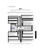
SELECT AMI OR B8ZS CODING FOR WAYSIDE DS1 LINE. SELECT ON TO DISABLE ALARM REPORTING FOR WAYSIDE DS1 LINE. SELECT OFF TO REPORT ALL ALARMS FOR THAT LINE. DS1 CARD A 1 DS1 LINES 2 DS1 CARD B 3 1 2 3 ALARM LOCK OUT OFF OFF OFF OFF OFF OFF DS1 LINE CODING AMI AMI AMI AMI AMI AMI AIS INHIBIT OFF OFF OFF OFF OFF OFF AIS INSERT 1 1 1 1 1 1 Select All SELECT 1 (ALL ONES) OR 0 (ALL ZEROES) FOR ALARM INDICATION SIGNAL (AIS) LINE CODE.
SYSTEM ID: ELMC: TEST 1 RADIO TYPE: RADIO LINK ID: MDR-8000 OC3 RADIO CONFIG: OC3-3 HS Tx Visual/Audible RCV SWITCHING: Option Key: + RELAYS ON/NO None NS Rx HS Rx SD Rx FD Rx + = = = = NON-STANDBY HOT-STANDBY SPACE DIVERSITY SWITCHED RSL Alarm Enable BER Disable Stat/Prov/WaySide 2 Fiber 2 Fiber Switched 4 Fiber 4Fiber Switched Resulting Configurations (Provisioning Examples 7-1 thru 7-13) TO = FIBER CONFIGURATION IS SELECTED ON OC3 FACILITIES PROVISIONING SCREEN (FIG 7-6).
Note If installation at both ends of a hop are complete except for connecting to customer inputs/outputs and it is desirable to have an alarm-free system, alarm reporting on the incomplete connections can be disabled temporarily through provisioning. You can communicate over the hop even if you do not have the radio connected to customer OC3 and wayside DS1 inputs; however, you will alarm.
Radio Configuration Service Channel OC3 Facilities SYSTEM ID: ELMC: 203R2 RADIO LINK ID: RADIO TYPE: MDR-8000 OC3 OC3-3 RADIO CONFIG: SYSTEM ALARM: NS Tx None ATPC NS Tx Enabled HS Tx FD Tx Major/Minor RCV SWITCHING: Disable AGC OPTIONS: Option Key: 128 TCM NS Rx None A&BRx PA Present NS HS Rx SD Rx ON/NO RELAYS FD Rx BER=1x10⁻⁶ Repeater TBOS Display 1 Service Channel OC3 Facilities 2 Fiber Frame B1 2 Fiber &Switched 4 Fiber 1:27:15 PM USI Version R1.
Radio Configuration Service Channel OC3 Facilities SYSTEM ID: ELMC: 203R2 RADIO LINK ID: RADIO TYPE: MDR-8000 OC3 OC3-3 RADIO CONFIG: SYSTEM ALARM: NS Tx None ATPC NS Tx Enabled HS Tx FD Tx Major/Minor RCV SWITCHING: Disable AGC OPTIONS: Option Key: 128 TCM SD Rx None A&BRx PA Present NS HS Rx SD Rx ON/NO RELAYS FD Rx BER=1x10⁻⁶ Repeater TBOS Display 1 Service Channel MDR-8000 OC3 Controller Version R1.
Radio Configuration Service Channel OC3 Facilities SYSTEM ID: ELMC: 203R2 RADIO LINK ID: RADIO TYPE: MDR-8000 OC3 OC3-3 RADIO CONFIG: NS Tx None ATPC NS Tx Enabled HS Tx FD Tx Major/Minor SYSTEM ALARM: RCV SWITCHING: Disable AGC OPTIONS: Option Key: 128 TCM SD Rx None A&BRx PA Present NS HS Rx SD Rx ON/NO RELAYS FD Rx BER=1x10⁻⁶ Repeater TBOS Display 1 Service Channel RSL Alarm Disable WaySide DS1 Facilities OC3 Facilities 2 Fiber Switched Fiber Configuration Tuessday, March 7, 2000
Radio Configuration Service Channel OC3 Facilities SYSTEM ID: ELMC: 203R2 RADIO LINK ID: RADIO TYPE: MDR-8000 OC3 OC3-3 RADIO CONFIG: SYSTEM ALARM: HS Tx None ATPC NS Tx Enabled HS Tx FD Tx Major/Minor RCV SWITCHING: Disable AGC Option Key: OPTIONS: Radio Configuration Tuessday, March 7, 2000 Disable 128 TCM SD Rx None A&BRx PA Present NS HS Rx SD Rx ON/NO RELAYS FD Rx BER=1x10⁻⁶ Repeater TBOS Display 1 RSL Alarm Disable Stat/Prov/WaySide Service Channel WaySide DS1 Facilities OC3 Fac
Radio Configuration Service Channel OC3 Facilities SYSTEM ID: ELMC: 203R2 RADIO LINK ID: RADIO TYPE: MDR-8000 OC3 OC3-3 RADIO CONFIG: SYSTEM ALARM: HS Tx None ATPC NS Tx Enabled HS Tx FD Tx Major/Minor RCV SWITCHING: Disable AGC OPTIONS: Option Key: 128 TCM HS Rx None A&BRx PA Present NS HS Rx SD Rx ON/NO RELAYS FD Rx BER=1x10⁻⁶ Repeater TBOS Display 1 Service Channel WaySide DS1 Facilities OC3 Facilities 2 Fiber Frame B1 2 Fiber &Switched 4 Fiber 1:27:15 PM USI Version R1.
Radio Configuration Service Channel OC3 Facilities SYSTEM ID: ELMC: 203R2 RADIO LINK ID: RADIO TYPE: MDR-8000 OC3 OC3-3 RADIO CONFIG: SYSTEM ALARM: HS Tx None ATPC NS Tx Enabled HS Tx FD Tx Major/Minor RCV SWITCHING: Disable AGC Option Key: OPTIONS: Radio Configuration WaySide DS1 Facilities Disable 128 TCM HS Rx None A&BRx PA Present NS HS Rx SD Rx ON/NO RELAYS FD Rx BER=1x10⁻⁶ Repeater TBOS Display 1 RSL Alarm Disable Stat/Prov/WaySide Service Channel WaySide DS1 Facilities OC3 Faci
Radio Configuration Service Channel OC3 Facilities SYSTEM ID: ELMC: 203R2 RADIO LINK ID: RADIO TYPE: MDR-8000 OC3 OC3-3 RADIO CONFIG: SYSTEM ALARM: HS Tx None ATPC NS Tx Enabled HS Tx FD Tx Major/Minor RCV SWITCHING: Disable AGC Option Key: OPTIONS: Radio Configuration WaySide DS1 Facilities Disable 128 TCM HS Rx None A&BRx PA Present NS HS Rx SD Rx ON/NO RELAYS FD Rx BER=1x10⁻⁶ Repeater TBOS Display 1 RSL Alarm Disable Stat/Prov/WaySide Service Channel WaySide DS1 Facilities OC3 Faci
Radio Configuration Service Channel OC3 Facilities SYSTEM ID: ELMC: 203R2 RADIO LINK ID: RADIO TYPE: MDR-8000 OC3 OC3-3 RADIO CONFIG: HS Tx None ATPC NS Tx Enabled HS Tx FD Tx Major/Minor SYSTEM ALARM: RCV SWITCHING: Disable AGC OPTIONS: Option Key: 128 TCM SD Rx None A&BRx PA Present NS HS Rx SD Rx ON/NO RELAYS Repeater TBOS Display 1 WaySide DS1 Facilities OC3 Facilities 2 Fiber 2 Fiber Frame B1 2 Fiber &Switched 4 Fiber 1:27:15 PM USI Version R1.
Radio Configuration Service Channel OC3 Facilities SYSTEM ID: ELMC: 203R2 RADIO LINK ID: RADIO TYPE: MDR-8000 OC3 OC3-3 RADIO CONFIG: SYSTEM ALARM: HS Tx None ATPC NS Tx Enabled HS Tx Major/Minor FD Tx SD Rx None A&BRx PA Present NS HS Rx SD Rx RELAYS ON/NO RCV SWITCHING: Disable AGC BER=1x10⁻⁶ Option Key: OPTIONS: Radio Configuration WaySide DS1 Facilities Disable 128 TCM Repeater TBOS Display 1 Stat/Prov/WaySide Service Channel RSL Alarm Disable WaySide DS1 Facilities OC3 Facilities
Radio Configuration Service Channel OC3 Facilities SYSTEM ID: ELMC: 203R2 RADIO LINK ID: RADIO TYPE: MDR-8000 OC3 OC3-3 RADIO CONFIG: SYSTEM ALARM: HS Tx None ATPC NS Tx Enabled HS Tx FD Tx Major/Minor RCV SWITCHING: Disable AGC Option Key: OPTIONS: Radio Configuration WaySide DS1 Facilities Disable 128 TCM HS Rx None A&BRx PA Present NS HS Rx SD Rx ON/NO RELAYS FD Rx BER=1x10⁻⁶ Repeater TBOS Display 1 Stat/Prov/WaySide Service Channel Section OH Insertion Tuessday, March 7, 2000 2 Fi
Radio Configuration Service Channel OC3 Facilities SYSTEM ID: ELMC: 203R2 RADIO LINK ID: RADIO TYPE: MDR-8000 OC3 OC3-3 RADIO CONFIG: SYSTEM ALARM: HS Tx None ATPC NS Tx Enabled HS Tx FD Tx Major/Minor RCV SWITCHING: Disable AGC Option Key: OPTIONS: Radio Configuration Tuessday, March 7, 2000 Disable 128 TCM SD Rx None A&BRx PA Present NS HS Rx SD Rx ON/NO RELAYS FD Rx BER=1x10⁻⁶ Repeater TBOS Display 1 RSL Alarm Disable Stat/Prov/WaySide Service Channel OC3 Facilities WaySide DS1 Fac
Radio Configuration Service Channel OC3 Facilities SYSTEM ID: ELMC: 203R2 RADIO LINK ID: RADIO TYPE: MDR-8000 OC3 OC3-3 RADIO CONFIG: SYSTEM ALARM: HS Tx None ATPC NS Tx Enabled HS Tx FD Tx Major/Minor RCV SWITCHING: Disable AGC Option Key: OPTIONS: Radio Configuration WaySide DS1 Facilities Disable 128 TCM HS Rx None A&BRx PA Present NS HS Rx SD Rx ON/NO RELAYS FD Rx BER=1x10⁻⁶ Repeater TBOS Display 1 RSL Alarm Disable Stat/Prov/WaySide Service Channel OC3 Facilities WaySide DS1 Faci
Radio Configuration Service Channel OC3 Facilities SYSTEM ID: ELMC: 203R2 RADIO LINK ID: RADIO TYPE: MDR-8000 OC3 OC3-3 RADIO CONFIG: SYSTEM ALARM: HS Tx None ATPC NS Tx Enabled HS Tx FD Tx Major/Minor RCV SWITCHING: Disable AGC Option Key: OPTIONS: Radio Configuration Tuessday, March 7, 2000 Disable 128 TCM HS Rx None A&BRx PA Present NS HS Rx SD Rx ON/NO RELAYS FD Rx BER=1x10⁻⁶ Repeater TBOS Display 1 RSL Alarm Disable Stat/Prov/WaySide Service Channel OC3 Facilities WaySide DS1 Fac
SELECT SUPERFRAME (SF) OR EXTENDED SUPERFRAME (ESF) TO MATCH FRAMING ON WAYSIDE DS1 INPUT. SELECT ON TO DISABLE ALARM REPORTING FOR WAYSIDE DS1 LINE. SELECT OFF TO REPORT ALL ALARMS FOR LINE. 1 DS1 LINES 2 3 1 2 3 ALARM DISABLE OFF OFF OFF OFF OFF OFF FRAME FORMAT ESF ESF ESF ESF ESF ESF LINE CODING ESF OFF SF OFF OFF OFF OFF OFF LINE LENGTH 0-133 0-33 0-33 0-33 0-33 0-33 Select All 0-133 133-266 133-266 133-266 133-266 MDR-1018 05/05/04 SELECT DISTANCE IN FT.
ONE MUST BE SELECTED FOR FUNCTION TO DISPLAY.
Note The 2-wire handset is transported over Audio 1 only. Note Audio provisioning is required only if 4-wire audio equipment (external equipment not part of the radio) is supplied and the external audio equipment is connected to audio port 1 J316 or audio port 2 J317 on the radio backplane. These provisionable 4-wire audio functions should not be confused with the 2-wire audio handset.
Note DTMF allows you to dialup and ring other sites using the 2-wire handset. Only the ringing is detected. Communication over the handset is party-line. DTMF addressing is a local function not a network function, therefore if one or more radios are assigned the same DTMF address, they will all ring when that address is dialed. To be able to use the DTMF function: 1. Audio 1 must be selected for 2-wire handset operation. 2. DTMF must be turned ON on the Audio provisioning screen. 3.
SELECT MCS RSS ON TO ALLOW CONTROLLER TO RESPOND WHEN REMOTE STATION SCANNER (RSS) IS POLLED. IF THIS OPTION IS TURNED OFF, CONTROLLER DOES NOT RESPOND WHEN RSS IS POLLED. REMOTE STATION SCANNER OPERATION IS AVAILABLE ONLY IF MCS IS SELECTED IN ONE OF THE SERVICE CHANNELS. MCS ADDRESS–ALLOWS USER TO ENTER AN MCS ADDRESS IF MCS-11 HAS BEEN SELECTED IN ONE OF THE SERVICE CHANNELS.
Note MCS-11 is enabled/disabled using the service channel 1-3 selections. MCS-11 must be enabled for MCS-11/PPP transport operation. SELECT PORTS ON I/O INTFC MODULE. SERVICE CHANNEL IS INSERTED/DROPPED.
PROVISION ANY ONE OR ALL RADIOS AT A SITE, LOCALLY, USING FOLLOWING PROCEDURE: 1. SINGLE CLICK TO PLACE CURSOR HERE. ELMC SYSTEM ID: 6. TYPE IN DESCRIPTION (IF DESIRED). J7914 5. TYPE IN 5-CHARACTER ADDRESS. MUST MATCH ADDRESS IN STEP 1 EXACTLY. RADIO LINK ID: Disable 2. BACKSPACE TO DELETE CURRENT ELMC ADDRESS (IF ANY). 3. ENTER 5-CHARACTER ELMC ADDRESS. 7. CLICK HERE TO ENTER NEW ADDRESS AND DESCRIPTION 4. OPEN ELMC ADDRESS SETUP SCREEN.
SELECT TIME LOCALLY FOR ELMC RESPONSE TO A REQUEST FOR STATUS BEFORE TRYING AGAIN. SELECT SHORTER TIME (5 SECS) FOR SHORTER SYSTEMS (10 HOPS OR LESS). SELECT LONGER TIME (10 SECS) FOR SYSTEMS WITH 10 HOPS OR MORE.
NOTE: DEFAULT CONTROL NAMES ARE USER CONTROL 1-6 1. OPEN USER CONTROL NAMES SETUP SCREEN 2. SELECT RADIO User Control Names Setup -- MDR-8000 CONTROL NAMES ELMC List RACK1 RACK2 RACK3 RACK4 ----- DURANGO DURANGO RED MTH PASS SILVERTON GEN START TWR LIGHT OVRD User Control #3 User Control #4 User Control #5 OK CLICK HERE TO SAVE CANCEL APPLY User Control #6 CLICK HERE TO CANCEL TRANSACTIONS BEFORE SAVE 3. SELECT CONTROL POINT 4.
1. SELECT RADIO CLICK HERE TO SAVE Alcatel User Interface – [Provisioning MDR-8000 OC3] File View Setup Options F3 F4 Prov.
5 MAINTENANCE GENERAL This section contains information and procedures to aid in restoring the equipment to its proper operating condition after it has been determined that a problem exists. 5.1 The following warnings and cautions apply while operating, performance testing, troubleshooting, or repairing the MDR-8000 series radios. DANGER Possibility of Injury to Personnel Short circuits in low-voltage, low-impedance dc circuits can cause severe arcing that may result in burns or eye injury.
CAUTION Possibility of Service Interruption RF flex coaxial cable requires special consideration. The electrical characteristics of the coax can be affected if it is accidentally twisted or bent. Provide mechanical support to prevent any weight or strain to the coax and connector when connecting or disconnecting equipment. Loosen the connectors at both ends of a coax section if one end must be moved even slightly.
PERIODIC CHECK FAILURE* PERFORMANCE DOES NOT MEET ESTABLISHED STANDARDS ALARM INDICATION PERFORM TROUBLE ANALYSIS CHECKS AND ADJUSTMENTS REQUIRED* CAUSE OF ALARM MODULE REPLACEMENT REQUIRED REFER TO MODULE REPLACEMENT TABLE MODULE ADJUSTMENT REQUIRED NO YES PERFORM APPLICABLE CHECKS AND ADJUSTMENTS* MAINTENANCE COMPLETE YES PROBLEM RESOLVED NO PERFORM ADDITIONAL TROUBLESHOOTING USING THEORY AND DIAGRAMS SECTION AS REQUIRED TO RESOLVE PROBLEM *IF APPLICABLE MW300–0843–2 Figure 5-1 Maintenan
5.3 SPECIAL TOOLS Refer to Table 5-1 for special tools required for maintenance. Similar tools can be substituted for those recommended; however, before substitution, check the minimum parameters.
AE–37( ) CNTLR C1 MDR–8000 SHELF TO CONNECTOR J301 (CONNECTS TO AE–37 CONTROLLER) RS–232C INTERFACE CABLE USI TERMINAL RS–232C PORT MW211–0066–1 101598 Figure 5-2 USI Computer to Controller Interconnection 5-5
RECOMMENDED PERIODIC CHECKS Perform local oscillator frequency verification, receive local oscillator frequency verification, and transmitter output check 1 year after initial setting and at 5-year intervals thereafter to correct possible drift caused by aging. 5.6 TROUBLESHOOTING The digital radio system is equipped with alarm circuitry and automatic switching (in hotstandby, frequency diversity, and space diversity configurations) to provide protection against loss of traffic.
TRANSMITTER STATUS A XMT OnLine XMT Provisioning Common Loss PA TEMPERATURE LIMITS PA Temperature EXCEEDED. CHECK PA Power MOUNTING SCREWS. Transmit Power ATPC High Power ATPC HAS BEEN ACTIVE ATPC Timeout FOR 5 MINUTES WITHOUT Sync Loss RETURNING TO NORMAL (DROPS BACK TO LOW POWER ONLY IF ATPC HAS BEEN ENABLED WITH TIMEOUT). SILENT FAILURE (NO ALARM ACTIVATED) AT TRANSMITTER.
LOSS OF XMT SIGNAL DETECTED AT OUTPUT OF PA. IF ANY OTHER ALARMS ARE RED, GO TO 1. IF NOT GO TO 2. 1. IF OFF NORMAL ALARM IS LIT, CHECK 10.5 V SWITCH ON POWER SUPPLY IS ON. IF NOT REMOVE/REPLACE PA MODULE. 2. MEASURE RF LEVEL AT RF MON CONNECTOR ON XMTR MODULE. IF LEVEL IS LOW, GO TO 3. IF NOT, GO TO 4. 3. MEASURE FREQUENCY AT XTAL MON CONNECTOR ON XMTR MODULE. IF FREQUENCY IS CORRECT, REMOVE/REPLACE XMTR MODULE. IF NOT REMOVE/REPLACE XTAL OSCILLATOR SUBBOARD. 4. REMOVE/REPLACE I/O INTERFACE MODULE.
TRANSMITTER STATUS XMT On Line SEE DS1/E1 XMT ALARMS XMT PROV, FIG 5-3 XMT Provisioning DS3 I/O INTFC CANNOT RECOVER FRAMING FROM B INCOMING DS3 SIGNAL OR THERE IS NO INPUT SIGNAL. IS DS3 AIS Detect ALARM ON? YES, TROUBLESHOOT UPSTREAM RADIOS AND EXTERNAL MUX Common Loss PA Temperature SEE DS1/E1 XMT ALARMS, FIG 5-3 A EQUIPMENT. NO, CHECK INPUT SIGNAL. IF INPUT SIGNAL PA Power IS OK, REPLACE DS3 I/O INTFC. Transmit Power IF NOT, TROUBLESHOOT EXTERNAL ATPC High Power MUX EQUIPMENT.
TRIGGERS WHEN BOTH A AND B RCVRS HAVE LOF. THIS INITIATES A REQUEST TO SWITCH XMTRS AT FAREND. WHEN RSL IS MORE POSITIVE THAN - 50 DBM, FAREND XMTR SWITCHES IN 5 SECONDS AND THEN SWITCHES EVERY 30 SECONDS UNTIL ALARM CLEARS. AFTER XMTR SWITCHES 10 TIMES, THE I/O INTERFACE MODULE SWITCHES. THIS SEQUENCE OF EVENTS CONTINUES UNTIL ALARM CLEARS. TROUBLESHOOT FAREND XMTRS. Note In order to clear a CLA, it must be acknowledged locally (at radio indicating alarm) using front panel control on controller module.
COMMUNICATION FAILURE BETWEEN CONTROLLER AND LOSS OF SIGNAL LOCK IN RCVR. RCVR. MAY BE CAUSED BY MISMATCH BETWEEN MAY BE DUE TO LOSS OF RCV SIGNAL CAPACITY KEYS. IF BOTH A AND B SIDES ARE ALARMED, OR LO OFF FREQUENCY REMOVE/REPLACE CONTROLLER. IF ONLY ONE SIDE IS 1. VERIFY RSL ON ANALOG MONITOR ALARMED, CHECK RCVR CAPACITY KEY ON FAILED SIDE. SCREEN. IF RSL IS OK, GO TO 2. IF NOT GO TO 3. 2. VERIFY RCVR XTAL FREQUENCY. IF FREQUENCY IS CORRECT, DEGRADED SIGNAL. NORMALLY REMOVE/REPAIR RCVR.
RECEIVER STATUS RCV On Line SEE DS1/E1 RCV ALARMS RCV PROV, FIG 5-5 RCV Provisioning Channel Fail SEE DS1/E1 RCV ALARMS, FIG 5-5 Radio Frame Loss Eye Closure A B I/O INTERFACE CANNOT RECOVER FRAMING FROM SIGNAL FROM RCVR MODULE. 1. IS DS3 AIS Detect ALARM ON? YES, CHECK FOR UPSTREAM XMTR DS3 AIS Detect ALARM. IF XMTR DS3 AIS Detect ALARM IS ON, TROUBLESHOOT EXTERNAL MUX EQUIPMENT AT XMT END. IF NOT, TROUBLESHOOT UPSTREAM XMTR. NO, GO TO 2. 2.
I/O CONDITIONER CANNOT RECOVER FRAMING FROM SIGNAL FROM RCVR MODULE. 1. IS OC3 AIS-L Detect ALARM ON? YES, CHECK FOR UPSTREAM XMTR OC3 AIS-L Detect ALARM. IF XMTR OC3 AIS Detect ALARM IS ON, TROUBLESHOOT EXTERNAL MUX EQUIPMENT AT XMT END. RECEIVER STATUS SUMMARY ALARM FOR RCVR. Receiver Fault A IF NOT, TROUBLESHOOT UPSTREAM XMTR. B NO, GO TO 2. 2. IS RADIO HOT-STBY? YES Receiver On Line Channel Fail Eye Closure SEE DS1/E1 RCV ALARMS, FIGURE 5-5 Low RSL A.
COMMUNICATION FAILURE BETWEEN CONTROLLER AND ONE OR MORE DS1/E1 INTERFACE ASICS ON I/O INTERFACE MODULE. 1. IF A AND B ALARMS ARE ACTIVE, REPLACE CONTROLLER. 2. REPLACE I/O INTERFACE. VOLTAGE REGULATION FAILURE OR EXCESSIVE LOAD. 1. CYCLE POWER 2. CHECK FUSE 3. CHECK OUTPUT POWER 4. REPLACE POWER SUPPLY COMMON STATUS CLICK HERE, DROP DOWN LIST DISPLAYS ONE OR MORE MESSAGES. TROUBLESHOOT AS FOLLOWS. A I/O On Line DS1 Provisioning Power Regulator Command Path CONTROLLER MODULE FAILURE. 1.
VOLTAGE REGULATION FAILURE OR EXCESSIVE LOAD. 1. CYCLE POWER 2. CHECK FUSE 3. CHECK OUTPUT POWER 4. REPLACE POWER SUPPLY MISMATCH BETWEEN PROVISIONING DATA WRITTEN TO I/O INTERFACE BY CONTROLLER AND THEN READ BY CONTROLLER. 1. REPROVISION AND SAVE. 2. REPLACE I/O INTERFACE MODULE. CLICK HERE, DROP DOWN LIST DISPLAYS ONE OR MORE MESSAGES. TROUBLESHOOT AS FOLLOWS. COMMON STATUS A I/O On Line DS1 Provisioning B LOSS OF COMMUNICATION BETWEEN CONTROLLER AND FAREND CONTROLLER. 1. VERIFY RCVR OPERATION. 2.
SUMMARY ALARM FOR I/O INTERFACE MODULE IS PRESENT, BUT CANNOT COMMUNICATE WITH CONTROLLER ON I2C BUS. 1. REMOVE AND REPLACE MODULE INDICATING READ FAIL ON INVENTORY SCREEN. 2. REMOVE AND REPLACE CONTROLLER. COMMON A STATUS B I/O Interface Fault LOSS OF COMMUNICATION BETWEEN CONTROLLER AND FAREND CONTROLLER. 1. VERIFY RCVR OPERATION. 2. REPLACE CONTROLLER. Power Supply Inventory CLICK HERE, DROP DOWN LIST DISPLAYS ONE OR MORE MESSAGES. TROUBLESHOOT AS FOLLOWS.
LOSS OF INPUT SIGNAL TO I/O INTERFACE, INABILITY TO RECOVER 1 CLOCK ON ALARMED LINE, OR BIPOLAR VIOLATION DETECTION A B 1. CHECK PRESENCE AND QUALITY OF DS1/E1 INPUT TO RADIO. DS1 LINE # 2. REPLACE I/O INTERFACE MODULE. SIDES TX SIG TRANSMIT HARDWARE FAILURE OR BUFFER SPILLS TX ALM ON ALARMED LINE. RX ALM 1. VERIFY QUALITY OF TX INPUT DATA. 2. REPLACE I/O INTERFACE MODULE. LOSS OF RECEIVE CLOCK, BUFFER SPILLS, OR ALARM INSERTION SIGNAL ON THE ALARMED LINE.
LOSS OF INPUT SIGNAL TO I/O INTFC. 1. CHECK PRESENCE OF DS1 INPUT TO RADIO. 2. REPLACE I/O INTFC MODULE. WAYSIDE DS1 INABILITY TO RECOVER CLOCK OR BIPOLAR VIOLATION DETECTED ON DS1/E1 INPUT TO RADIO. 1. CHECK QUALITY OF DS1 INPUT TO RADIO. 2. REPLACE I/O INTFC MODULE. Xmtr/Rcvr On Line 1 2 3 1 2 3 Xmtr LOS 1 2 3 1 2 3 Xmtr LOF 1 2 3 1 2 3 Xmtr AIS Detect 1 2 3 1 2 3 Rcvr LOF 1 2 3 1 2 3 Rcvr AIS Detect 1 2 3 1 2 3 AIS DETECTED ON DS1 INPUT TO RADIO. FAULT IS EXTERNAL TO RADIO.
5.8 MODULE REPLACEMENT WARNING Possibility of Damage to Equipment Modules screwed to heat sink must be screwed securely before power is turned on. WARNING Possibility of Damage to Equipment Units with the electrostatic-sensitive (ESS) symbol contain ESS devices. Store these units in an antistatic container when not in use, and anyone handling a unit should observe antistatic precautions. Damage to the unit may result if antistatic protection is not maintained.
CAUTION Possibility of Service Interruption Modules may be removed or installed with shelf power applied. However, exercise reasonable care to prevent contacting adjacent modules. If clearances are narrow, consider setting the power supply to OFF while the module is being removed or replaced. (Before setting any switch to OFF, verify that traffic has been protected.) Before replacing any module, refer to Table 5-2 to determine the actions, other than physical replacement, required.
Table 5-2 Module Replacement Matrix MODULE/UNIT REMOVAL/REPLACEMENT PROCEDURE CHECKS/ADJUSTMENTS PROCEDURE AE-27AF Relay Interface No Special Procedure Required None Required AE-37Y Controller Chart 2 None Required CE-16BB Power Supply Chart 1 None Required Fuse No Special Procedure Required. Refer to Operations Section for Location.
5.9 CHANGING FREQUENCY CAUTION Possibility of Service Interruption Crystals are soldered and tuned up in a crystal oscillator subboard at the factory. Changing frequencies requires changing the crystal on the crystal oscillator subboard in the transmitter and receiver modules. Changing out the crystal requires tuning the crystal oscillator subboard. Tuning the crystal oscillator subboard is a factory procedure. An RF frequency change of ±2 MHz requires re-tuning the diplexer.
Chart 1 Power Supply Removal and Replacement PURPOSE Use this procedure to remove and replace CE-16BB Power Supply. SPECIAL TOOLS REQUIRED Torque Screwdriver STEP PROCEDURE WARNING Possibility of Damage to Equipment Wear ground straps according to local office procedures. WARNING Possibility of Damage to Equipment Ensure the two mounting screws, accessible through the front panel, are loosened before attempting to remove power supply from shelf to prevent breaking handle.
STEP 1 PROCEDURE, CONTINUED Is radio protected (hot-standby or frequency diversity)? If yes, go to step 2. If no, go to step 3. 2 Use front panel OVRD controls on AE-37( ) Controller to switch and lock on-line opposite side XMTR, RCVR, and I/O to opposite side from failed power supply. 3 Do you want to remove or install power supply module? If remove, go to step 4. If install, go to step 7. REMOVE: 4 On failed power supply, set PA ON/OFF switch to OFF.
STEP 10 PROCEDURE, CONTINUED Is radio equipped with optional PA? If yes, go to step 11. If no, go to step 16. 11 On power supply, set PA ON/OFF switch to ON. Note DS3 and OC3 radios have provisioning data stored on both the controller and A-side power supply. When provisioning is saved through downloading, the provisioning data is stored on both modules.
P/O SHELF INSTALL: (INSTALL STEPS ARE PREFIXED BY LETTER "I"). REMOVE: (REMOVE STEPS ARE PREFIXED BY LETTER "R"). ALARM R1. SET PA POWER SWITCH TO OFF. OFF NORM I1. VERIFY JOINING SURFACES ON POWER SUPPLY AND HEATSINK ARE CLEAN. I2. INSERT POWER SUPPLY IN SHELF AND LATCH TOP AND BOTTOM INSERTION AND EXTRACTION HANDLES. I3. TIGHTEN SCREWS. TORQUE SCREWS TO 19 IN. LBS. I4. SET POWER SWITCH TO ON. ON 1 POWER R2. SET POWER SWITCH TO OFF. OFF 0 +10.5V R3. LOOSEN MOUNTING SCREWS.
Chart 2 Controller Removal and Replacement PURPOSE Use this procedure to remove and replace AE-37Y Controller. SPECIAL TOOLS REQUIRED None STEP PROCEDURE WARNING Possibility of Damage to Equipment Wear ground straps according to local office procedures. CAUTION Possibility of Service Interruption This is an in service procedure, however protection switching is disabled. If another failure occurs during the performance of the procedure, service will be interrupted.
STEP PROCEDURE, CONTINUED INSTALL: 6 See Figure 5-16 and follow step-by step procedure to install controller module. LBO/OC3 AUX INTFC 1 REMOVE FAILED CONTROLLER J2 2 REMOVE ELMC OPTION KEY (IF EQUIPPED) 3 INSTALL REMOVED ELMC OPTION KEY FROM STEP 2 ON REPLACEMENT CONTROLLER. 4 INSTALL REPLACEMENT CONTROLLER IN SHELF.
Note A replacement controller that is loaded with the same firmware load as the controller that is being replaced (i.e.: controller for DS3 radio is replacing a DS3 radio controller) is automatically rebooted and provisioned to match the module it is replacing. If the replacement controller is for a different type of radio (i.e.; controller for a DS3 radio is being used to replace a controller in a DS1 or OC3 radio), the controller alarm will flash when the replacement module is installed in the shelf.
6 CLICK HERE PROVISIONING HOLD MESSAGE DISPLAYS. 7 CLICK HERE Alcatel User Interface File View Setup Options Communication Options F6 F5 F4 New Controller Alarm Status F7 Performance Station Alarm F8 F9 User Control Provisioning Firmware Upgrade LOCAL MAIN ELMC Address Diagnostics ELMC Descriptions Communicating*** Prov. Hold TDE Chip Receive Provisioning NOTE PROVISIONING HOLD MESSAGE IS DISPLAYED ON ALL SCREENS. THE MESSAGE IS REMOVED WHEN PROVISIONING IS SAVED.
8 CLICK HERE 10 CLICK HERE 9 CLICK HERE Alcatel User Interface File View Setup Options Communication Options F6 F5 F4 New Controller Alarm Status F7 Performance Firmware Upgrade F8 Station Alarm User Control Download LOCAL MAIN ELMC Address Diagnostics ELMC Descriptions F9 Provisioning Prov. Hold Communicating*** TDE Chip Receive Provisioning Please Select a Filename in the Following Drive Directory before Downloading CSS0038.DAT 38.DAT CSS00 c: 12 c:\ windnld CLICK ON LATEST FILE (HIG
Chart 3 I/O Interface Removal and Replacement PURPOSE Use this procedure to remove and replace DX-35( ) I/O Interface module. SPECIAL TOOLS REQUIRED None STEP PROCEDURE WARNING Possibility of Damage to Equipment Wear ground straps according to local office procedures. CAUTION Possibility of Service Interruption This is an out-of-service procedure when on a nonstandby (unprotected) system. On a hot-standby or frequency diversity system, switch traffic on the channel under test to protect.
STEP PROCEDURE, CONTINUED 5 On front panel of controller module, press and hold ACO LT/OVRD switch in ACO LT (lamp test) position until TX, RX, and I/O ON LINE LEDs on front of controller flash (approximately 5 seconds wait). 6 Release ACO LT/OVRD switch. 7 Disconnect fiber optic cables. 8 Remove I/O interface module from shelf. INSTALL: 9 10 Install I/O interface module in shelf. Is I/O interface module DX-35P OC3 I/O Interface? If yes, go to step 11. If no, go to step 15.
Chart 4 XMTR Removal and Replacement CAUTION Possibility of Service Interruption XMTR Crystals should never be shipped as replacements without being soldered and tuned up in an oscillator assembly board at the factory.
STEP PROCEDURE, CONTINUED WARNING Possibility of Damage to Equipment Wear ground straps according to local office procedures. 1 Do you want to remove or install XMTR module? If remove, go to step 2. If install, go to step 8. REMOVE: 2 Is radio protected (hot-standby or frequency diversity)? If yes, go to step 3. If no, go to step 4. 3 Use front panel OVRD controls on AE-37( ) Controller to lock on-line XMTR (opposite side from failed XMTR) on line.
STEP PROCEDURE, CONTINUED INSTALL: 8 On replacement XMTR module, install XMTR crystal oscillator subboard. See Figure 5-17. 9 On replacement XMTR module, install XMTR capacity key. See Figure 5-18. 10 Install replacement XMTR module in card cage. 11 Perform XMT Crystal Oscillator Frequency Checks and Adjustment procedure. Refer to Appendix E. 12 Is radio equipped with optional PA? If no, Perform XMTR Output Level Checks and Adjustment (No PA) procedure. Refer to Appendix E.
REMOVE: (REMOVE STEPS ARE PREFIXED BY LETTER “R”). R1. REMOVE TRANSMITTER FROM CARD CAGE. R2. REMOVE 8 SCREWS FROM CR YSTAL OSC SUBBOARD COVER, AND REMOVE COVER. XMTR- RIGHT SIDE VIEW R3. DISCONNECT RIBBON CABLE FROM J8. R4. REMOVE 3 MOUNTING SCREWS, AND REMOVE CRYSTAL OSC SUBBOARD. INSTALL (INSTALL STEPS ARE PREFIXED BY LETTER “I”). I1. PLACE CRYSTAL OSC SUBBOARD IN MOUNTING CAVITY Note J8 CRYSTAL OSC SUBBOARD Ensure board edge does not make contact with chassis wall. I2. INSTALL 3 MOUNTING SCREWS. I3.
CAUTION Possibility of Service Interruption REMOVE: (REMOVE STEPS ARE PREFIXED BY THE LETTER "R"). This is an out-of-service procedure when on a nonstandby (unprotected) system. On a hotstandby or frequency diversity system, switch traffic on the channel under test to protect. R1. REMOVE TRANSMITTER FROM CARD CAGE. R2. REMOVE 13 SCREWS FROM CAPACITY KEY AND REMOVE CAPACITY KEY. INSTALL: (INSTALL STEPS ARE PREFIXED BY THE LETTER "I"). I1. I2. INSTALL CAPACITY KEY ON THREE CONNECTORS. INSTALL 13 SCREWS.
Chart 5 RCVR Removal and Replacement CAUTION Possibility of Service Interruption XMTR Crystals should never be shipped as replacements without being soldered and tuned up in an oscillator assembly board at the factory.
STEP PROCEDURE, CONTINUED WARNING Possibility of Damage to Equipment Wear ground straps according to local office procedures. CAUTION Possibility of Service Interruption This is an out-of-service procedure when on a nonstandby (unprotected) system. On a hot-standby, space diversity, or frequency diversity system, switch traffic on the channel under test to protect. 1 Is radio protected (hot-standby or frequency diversity)? If yes, go to step 2. If no, go to step 3.
STEP PROCEDURE, CONTINUED 6 On RCVR module being replaced, remove RCVR crystal oscillator subboard. See Figure 5-19. Retain for installation on replacement module. 7 On RCVR module being replaced, remove RCVR capacity key. See figure 2. Retain for installation on replacement module. INSTALL: 8 On replacement RCVR module, install RCVR crystal oscillator subboard. See Figure 5-19. 9 On replacement RCVR module, install RCVR capacity key. See Figure 5-20.
REMOVE: (REMOVE STEPS ARE PREFIXED BY LETTER “R”). R1. REMOVE RECEIVER FROM CARD CAGE. R2. REMOVE 8 SCREWS FROM CR YSTAL OSC SUBBOARD COVER, AND REMOVE COVER. RCVR–RIGHT SIDE VIEW R3. DISCONNECT RIBBON CABLE FROM J8. R4. REMOVE 3 MOUNTING SCREWS, AND REMOVE CRYSTAL OSC SUBBOARD. INSTALL: (INSTALL STEPS ARE PREFIXED BY LETTER “I”). I1. PLACE CRYSTAL OSC SUBBOARD IN MOUNTING CAVITY. J8 CRYSTAL OSC SUBBOARD Note Ensure board edge does not make contact with chassis wall. I2. INSTALL 3 MOUNTING SCREWS. I3.
REMOVE: (REMOVE STEPS ARE PREFIXED BY LETTER ‘R’). R1. REMOVE RCVR FROM CARD CAGE. R2. REMOVE 13 SCREWS FROM CAPACITY KEY AND REMOVE CAPACITY KEY. INSTALL: (INSTALL STEPS ARE PREFIXED BY LETTER ‘I’). RCVR–RIGHT SIDE VIEW I1. INSTALL CAPACITY KEY ON THREE CONNECTORS. MW211–0069–1 101598 I2. INSTALL 13 SCREWS.
Chart 6 PA Removal and Replacement PURPOSE Use this procedure to remove and replace UD-51( ) PA. SPECIAL TOOLS REQUIRED None STEP PROCEDURE DANGER Possibility of Injury to Personnel Exposure to energy radiated at microwave frequencies can cause eye injury and eventual blindness. Do not operate the system with a waveguide port unterminated. WARNING Possibility of Damage to Equipment Wear ground straps according to local office procedures.
STEP PROCEDURE, CONTINUED 2 Use front panel OVRD controls on AE-37( ) Controller to lock on-line XMTR (opposite side from failed XMTR) on line. 3 Do you want to remove or install PA module? If remove, go to step 4. If install, go to step 6. REMOVE: WARNING Possibility of Damage to Equipment Check to ensure that the three mounting screws securing the PA to the heatsink are loose before attempting to remove the PA to prevent damage to the module. 4 Remove PA from shelf. See Figure 5-21.
STEP PROCEDURE, CONTINUED INSTALL WARNING Possibility of Damage to Equipment The PA to heatsink mounting is critical. The three screws securing the PA to the heat sink must be tightened to 19 in-lbs using a torque wrench and not over/under-tightened. Improper mounting will cause over-heating and alarm and shut off power to the PA. This will result in loss of traffic on unprotected systems. On protected systems, a switch to the off-line PA will occur. 5 Install PA in shelf. See Figure 5-21.
FRONT PANEL P/O SHELF REMOVE: (REMOVE STEPS ARE PREFIXED BY LETTER 'R'). DC MON INSTALL: (INSTALL STEPS ARE PREFIXED BY LETTER 'I'). GND PWR ALM R3. LOOSEN MOUNTING SCREWS AND SLIDE PA TOWARD FRONT OF CARD CAGE TO ACCESS RF OUT CONNECTOR TEMP ALM DC MON ADJ PWR ALM ADJ 10.5V DC POWER AMPLIFIER R1. DISCONNECT CABLE FROM XMTR RF OUT CONNECTOR. RF MON RF IN I1. INSTALL REPLACEMENT PA IN SHELF AND TIGHTEN MOUNTING SCREWS (TORQUE TO 19 IN. LBS). I2 CONNECT RF OUT CABLE. I3.
Chart 7 Changing System Software PURPOSE This procedure provides instructions to change previously loaded software to a newer version. The procedure is written for DS3 but applies to DS1, DS3, and OC3 software and radios. TOOLS REQUIRED PC RS-232 interface cable PN 695-7848 GENERAL The system operating software for the AE-37( ) Controller can be changed through the USI port using the laptop computer.
STEP PROCEDURE, CONTINUED 1 Insert CD ROM disk into PC. 2 On Windows desktop, double click on My Computer icon. My Computer window displays. 3 In My Computer window, click on CD ROM icon. Files window displays. DOWNLOAD SOFTWARE TO PC 4 See Figure 5-23. Follow directions to download software to PC. 020604_0736 (Z:) File File Edit View Help STEP 1 Release Docume... setup.exe Setup.
STEP PROCEDURE, CONTINUED DOWNLOAD SOFTWARE TO RADIO CONTROLLER CAUTION Possibility of Service Interruption While the system software is being changed, all alarm monitoring and protection switching functions are suspended. If the system software change is interrupted before completion, the change is aborted and operation under the previous software resumes. 5 Connect RS-232 interface cable between USI port on controller and laptop computer. 6 Open Download screen (Start>Programs>WinUSI).
Alcatel User Interface File File View Setup Options F4 Communication F6 OptionsF6 F7 F8 F9 1 New Controller Alarm Status Analog Monitor Performance Firmware Upgrade Station Alarm User Control Provisioning Download LOCAL MAIN ELMC Address: 200R2 Description: Rack-A - bottom radio Communicating*** COM 1 200R2 Alcatel User Interface File File View Setup Options F4 F6 Alarm Status ELMC Address: Description: F6 Analog Monitor Performance F7 F8 Station Alarm F9 User Control Provisioni
STEP 1 Alcatel User Interface File File View Setup Options DOUBLE CLICK TO OPEN F4 ELMC LIST 2 F6 F6 F7 F8 F9 DOUBLE CLICK TO SELECT 1 Status Alarm REMOTE RADIO 3 SELECT OPTIONS/FIRMWARE UPGRADE/DOWNLOAD 4 Analog Monitor ELMC Address: 200R2 Description: Rack-A - bottom radio Performance Station Alarm User Control Provisioning LOCAL MAIN ELMC ADDRESS LIST Communicating*** DOUBLE CLICK TO SELECT Double Click on the Elmc to Select ADDRESS: DIRECTORY AND DISPLAY ALL FILES 5 CLICK ON D
A CommPak INDOOR SHELF The MDR-8000 CommPak indoor shelf (Figure A-1) is a reduced-size package for non-standby radio configurations. The CommPak indoor shelf operates the same as the MDR-8000 hot-standby shelf configured as a non-standby radio using the same software and equipped with the same modules with two exceptions: LBO and fan assembly. Figure A-1 Typical MDR-8000 CommPak Indoor Shelf This appendix describes the differences between the MDR-8000 hot-standby shelf and the CommPak indoor shelf.
CE-16BB PWR SUPPLY AE-37Y CNTR UD-36A( ) RCVR FAN ASSY LBO/OC3 AUX INTFC UD-51( ) PWR AMP UD-35A( ) XMTR DX-35M DS1/E1 I/O INTFC ALM ON LINE SYNC ALM ALM ON LINE COMMON LOSS ALM DX-35N DS3 I/O INTFC 01 XMT AUX SC ALM RCVR ON RAD LOF WYSD DS1 WYSD ALM 56 RAD DADE DS3 ALIGN 1 2 3 234 SELECT I/O INTFC MODULES BY DATA RATE 789 DX-35P OC3 I/O INTFC ALM WYSD ON INSVC OC3 IN WYSD ALM OC3 ALM OC3 OUT LMW-9080 08/29/03 Figure A-2 Typical MDR-8000 CommPak Indoor Shelf Component Locat
CE-16BB PWR SUPPLY AE-37Y CNTR FAN ASSY UD-51( ) PWR AMP UD-35A( ) XMTR UD-36( ) SINGLE RCVR EYE CLOSURE CHAN ALM ON LINE AFC MON EYE MON RSL MON GND RECEIVER XTAL MON RF IN SELECT RVCR BY FUNCTION UD-36( ) DUAL RCVR ON LINE CHANNEL ALM EYE CLOSURE M AFC A I EYE N RSL MN DV D I E S I T Y AFC V RSL EYE R GND RF IN DV XTAL DV RF IN MN XTAL MN DUAL RECEIVER AE-27AF RELAY INTFC AE-37AA TMN INTFC ALM 1 2 3 PPP E T H E R N E T SELECT ONE OR NONE LMW-9079 08/29/03 C R A F T
DS1/E1 LBO DS3 LBO OC3 AUX INTFC J26 J21 J202 J202 J23 J22 J25 J401 J305 J306 J303 J24 J314 J304 J203 J201 J201 SELECT LBO/AUX INTFC BY DATA RATE CE-16BB PWR SUPPLY AE-37Y CNTR UD-36A( ) RCVR FAN ASSY DX-35( ) I/O INTFC UD-35( ) XMTR UD-51( ) PWR AMP SELECT XTAL OSCILLATOR SUBBOARD BY CRYSTAL FREQUENCY. SELECT CAPACITY KEY BY DATA RATE. OC3 DS3 DS1/E1 SELECT OC3 CAPACITY KEY BY NUMBER OF LINES – 1 OR 3 LINES. SELECT DS3 CAPACITY KEY BY NUMBER OF LINES – 1, 2, OR 3 LINES.
A.1.1 External Fan Assembly See Figure A-3. The external fan assembly PN 3EM11901ABAA is required for cooling the CommPak indoor unit equipped with high-power amplifiers, for specific frequency bands, as follows: Radio Output Power MDR-8505u +30 dBm MDR-8506 +31 and +33 dBm MDR-8510/8511 +29 dBm The external fan assembly is wired to the CommPak indoor shelf internal fan assembly PN 3EM14510AAAA via cable.
DANGER Possibility of Injury to Personnel Short circuiting low-voltage, low-impedance dc circuits can cause arcing that may result in burns or eye injury. Remove rings, watches, and other metal jewelr y while working with primary circuits. Exercise caution to avoid shorting input power terminals. DANGER Possibility of Injury to Personnel To protect maintenance personnel from antenna tower lightning strikes, the ground system must be integrated by bonding frame ground and dc battery return together.
PIN 1 POS PIN 2 GND PIN 3 NEG J1 PWR CABLE ASSEMBLY PN695-7845-005 RED ORN SLIDE-ON LUG BLK CONNECT + BATT WIRE TO + RACK GND FOR POS GND INSTALLATIONS ORN 12 AWG CONNECT – BATT WIRE TO – RACK GND FOR NEG GND INSTALLATIONS BLK 12 AWG + BATT RED 12 AWG CHASSIS GND – BATT LMW-7224 01/22/04 Figure A-4 Power Cable Assembly Installation A-7
A.2.2 External Fan Assembly See Figure A-5 for interconnect details. INT.
FAN CABLE ASSY PN 3EM15115ABAA P302 J302 9 1 +12 VDC GND 9 1 FAN ALM CARD J1 P1 1 2 3 1 2 3 FAN ALM P105 J105 EXT FAN ASSY PN 3EM11901ABAA 2 2 FAN CARD (ON CommPak INDOOR SHELF) PN 3EM14508ABAA FAN CABLE ASSY PIN-OUT AND COLOR CODE FAN ALM 1 2 3 J302 J305 WIRE COLOR 2 RED BLK BLU 9 1 MDR-1024 06/09/04 Figure A-5 External Fan Assembly Interconnect Diagram (Sheet 2 of 2) A.2.
RACK GND 4 3 2 1 20 AMP 20 AMP 20 AMP 10 AMP FUSES E13 E14 E15 E16 E17 E18 1 AMP E25 E26 E27 E28 E29 E30 5 20 AMP 10 AMP E7 E8 E9 E10 E11 E12 6 10 AMP 6 1 AMP 5 1 AMP 4 1 AMP 3 10 AMP 20 AMP FUSES 20 AMP 2 20 AMP 1 20 AMP FUSE ALARM INDICATOR RACK GND E31 E32 E33 E34 E35 E36 WIRE WRAP ALARM INPUT ALARM OUTPUT J4 J5 J6 1 2 3 CUSTOMER 4 OUTPUTS 5 6 7 8 FUSE ALM J3 1 2 3 4 5 6 7 8 MAJOR 1 MINOR 1 MAJOR 2 MINOR 2 MAJOR 3 MINOR 3 MAJOR 4/AUX MINOR 4/AUX UNUSED NC COM NO PD
A.2.4 DS1 LBO Connections A.2.4.1 DS1 Cable Connections Recommended connectorized cable assembly – PN 695-7806-021 through -025 (22 AWG 12 pair shielded, jacketed cable with 25-pin D-type connector on one end). See Figure A-7 for shelf connector location and pinout. Refer to Table A-1 for mating cable wiring and color code.
Table A-1 DS1 IN J303 and DS1 OUT J304 Mating Cable CONNECTOR PIN NUMBER WIRE COLOR SIGNAL NAME 1 14 2 15 3 16 4 17 5 18 6 19 7 20 8 21 N/A N/A N/A N/A N/A N/A N/A N/A WHITE–BLUE BLUE–WHITE WHITE–ORANGE ORANGE–WHITE WHITE–GREEN GREEN–WHITE WHITE–BROWN BROWN–WHITE WHITE–SLATE SLATE–WHITE RED–BLUE BLUE–RED RED–ORANGE ORANGE–RED RED–GREEN GREEN–RED RED–BROWN BROWN–RED RED–SLATE SLATE–RED BLACK–BLUE BLUE–BLACK BLACK–ORANGE ORANGE–BLACK CHAN 1 TIP CHAN 1 RING CHAN 2 TIP CHAN 2 RING CHAN 3 TIP CHAN 3 RING CH
DS3 LBO CONNECTIONS A.2.5 The DS3 LBO compensates for the distance to the cross-connect for DS3 and wayside DS1 outputs. See Figure A-8 for connector locations.
A.2.5.1 DS3 Cable Connections Recommended connectorized cable assembly for all applications except repeaters, PN 632-4429-096/180 (8/15 ft RG-59B/U coax cable with straight male BNC connector on one end and right angle male BNC connector on other end). For repeater applications, recommend PN 632-4288-096/180 (8/15 ft RG-59B/U coax cable with straight male BNC connector on each end). See Figure A-8 for locations. A.2.5.
Recommended connectorized cable assembly – PN 695-7836-001/005 (25 pair shielded cable with 50 pin Amp connectors) (SCSI). See Figure A-8 for shelf connector location and pinout. Note Use repeater cables for cabling repeater shelf 1 to repeater shelf 2 (eastbound/westbound data/clock) A.2.
Refer to Table A-3 for recommended fiber optic jumpers. Table A-3 Fiber Optic Jumpers JUMPER TYPE PART NO. APPLICATION FC to LC 3EM07651AA-AK TERMINAL SC TO LC 3EM07646AA-AK TERMINAL LC TO LC 3EM07641AA-AK REPEATER A.2.7 OC3 AUX Interface Board Connections A.2.7.1 Wayside DS1 Terminal Recommended connectorized cable assembly – PN 695-4125-041 (26 AWG 5 pair shielded, jacketed cable with 9-pin D-type connector on one end). See Figure A-9 for location. A.2.7.
GND RPTR DS1 OUT TIP RPTR DS1 IN TIP J203 5 1 9 6 RPTR DS1 IN RING RPTR DS1 OUT RING FRONT VIEW J203 REPEATER J203 J202 J201 J202 WAYSIDE DS1 OUT J201 WAYSIDE DS1 IN 5 6 1 LINE 3 OUT TIP GND LINE 2 OUT TIP LINE 1 OUT TIP 9 LINE 1 OUT RING LINE 2 OUT RING LINE 3 OUT RING 1 FRONT VIEW J202 OUTPUT LINE 3 IN TIP GND LINE 2 IN TIP LINE 1 IN TIP 5 6 LINE 1 IN RING LINE 2 IN RING LINE 3 IN RING 9 J201 INPUT FRONT VIEW LMW-7222-SM 01/21/04 Figure A-9 OC3 AUX Interface Connector Location
Controller Cable Connection (J301) A.2.8 Recommended connectorized cable assembly – PN 695-7848-001 through 004 (24 AWG 6 pair shielded, jacketed cable with DEMM-9P connector on each end). See Figure A-10 for controller connector location and pinout. USI RI CTS RTS DSR J301 6 5 DCD RxD TxD DTR GND 1 9 J305 FRONT VIEW J315 J1 J318 J307 J316 J308 J317 J309 J312 J310 J301 LMW-7214 01/21/04 Figure A-10 Controller USI Connector J301 Location and Pinout A.2.
GND CALL DETECT AUDIO TIP OUT M LEAD AUDIO TIP IN J316/J317 5 1 9 6 AUDIO RING IN E LEAD AUDIO RING OUT CALL COMMON J305 FRONT VIEW J315 J1 J318 J307 J316 J308 J317 J309 J312 J310 J301 LMW-7215 01/21/04 Figure A-11 Audio Connectors J316 and J317 Location and Pinout A.2.10 RS-232 Cable Connections Recommended connectorized cable assembly – PN 695-4125-021 through 025 (26 AWG 5 pair shielded, jacketed cable with 9-pin D-type connector on each end).
GND RS232-2 OUT RS232-1 IN RS232-1 OUT J312 5 1 9 6 RS232-2 IN J305 FRONT VIEW J315 J1 J318 J307 J316 J308 J317 J309 J312 J310 J301 LMW-7216 01/21/04 Figure A-12 RS-232 Connect J312 Location and Pinout A.2.11 MCS-11 Cable Connections When MCS is selected to be placed on one of the three service channels and then RSS is enabled and properly addressed, applicable ports on the controller module are enabled.
A.2.11.1 MCS-11 Master (J307) Cable Connection Note If the radio is provisioned Repeater, port 2 on the controller, that connects to J307, is disabled. At a repeater, you can use J310 in lieu of J307 for connecting the TSM polling engine to the radio. MCS-11 connector J307 is used to connect to a TSM (-2500, -3500, or -8000) polling engine at a master terminal. Recommended connectorized cable assembly – PN 695-4126-007/009/012 (26 AWG 8 pair shielded, jacketed cable).
A.2.11.2 MCS-11 Repeater-to-Spur Daisy Chain Connection (J308/J309) Note MCS-11 must be provisioned MCS-11 J310 Master/Junction to enable XMT, RCV, and OUTPUT clocks. If an external modem is being used, provision MCS-11 for MCS-11 J310 Modem. This selection disables XMT, RCV,OUTPUT clocks and all MCS-11 clocks must now be provided by the external modem. MCS-11 connector J308/J309 is typically used to connect a repeater to a spur or multiple spurs in a daisy chain system configuration.
OFF HOOK + XMT DATA + CLK OUT + XMT CLK + RCV DATA + RCV CLK + J308 8 15 OFF HOOK + XMT DATA + 1 8 9 15 RCV CLK RCV DATA XMT CLK RTN CLK XMT DATA OFF HOOK - J305 J1 J318 J307 J316 J308 J317 J309 J312 J310 1 9 RCV CLK – RCV DATA – XMT CLK – FRONT VIEW FRONT VIEW J315 XMT CLK + RCV DATA + RCV CLK + J309 XMT DATA – OFF HOOK – J301 MDR-1010 04/08/04 Figure A-14 MCS-11 Connector J308 and J309 Location and Pinout A-23
A.2.11.3 MCS-11 Spur Connection (J310) MCS-11 connector J310 can be used to connect to a spur shelf and is the preferred connection to the DMX-3003N MUX. Recommended connectorized cable assembly – PN 695-4126-031 through -035 (26 AWG 8 pair shielded, jacketed cable with 15-pin D-type connector on each end). See Figure A-15 for shelf connector J310 location and pinout.
Recommended connectorized cable assembly – PN 695-4125-006/013 (26 AWG 5 pair shielded, jacketed cable). See Figure A-16 for shelf connectors locations and pinout. Note ELMC 1 connector J318 and ELMC 2 connector J315 are wired in parallel. You can connect J315 to J315, J315 to J318, or J318 to J318.
Note TBOS connections on J305 share pins with station alarms 13 through 16 and either TBOS or station alarms 13 through 16 is selected (provisioned) on the USI Radio Configuration Provisioning screen.
A.2.14 Station Alarm Wiring See Figure A-18. Use wire wrap adapter PN 695-4171-002 to connect station alarm inputs to the AE-27A Relay Interface module, via connector J305, in each rack. A typical connection scenario is shown. The station/shelf alarm for MCS-11 address A1A (MCS-11 alarm point 1) is connected by software. The station alarms for MCS-11 address A1B and A1C are assigned to MCS-11 Alarm points 2 and 3, respectively.
MAINTENANCE This part of the appendix provides information and procedures that are different for the hot-standby shelf and the CommPak indoor shelf. A.3 A.3.1 Warnings and Cautions All Warnings and Cautions outlined in the Maintenance section of the main book apply while operating, performance testing, troubleshooting, or repairing the MDR-8000 series radio. A.3.2 Troubleshooting Refer to the Maintenance section in the main book. A.3.
A.3.3.1 PA Module Removal and Replacement Remove and replace the PA using the following procedure: WARNING Possibility of Damage to Equipment Before starting removal procedure, loosen cable connected to RF OUT connector on PA. Semirigid coaxial cable requires special consideration. The electrical characteristics of the semirigid coax can be affected if it is accidentally twisted or bent.
2. DISCONNECT CABLE FROM RF OUT CONNECTOR ON XMTR.
WARNING Possibility of Damage to Equipment Check to ensure that the three mounting screws securing the PA to the heatsink are loose before attempting to remove the PA to prevent damage to the module. 4. LOOSEN THREE CAPTIVE MOUNTING SCREWS SECURING PA TO HEAT SINK. LEFT BRACKET 6. ANGLE PA TO LEFT AND PULL OUT ON RIGHT SIDE OF PA UNTIL LEFT SIDE OF CHASSIS COVER CLEARS BRACKET. 5. PULL STRAIGHT OUT ON PA UNTIL CHASSIS COVER MEETS LEFT BRACKET ON CARD CAGE. 2.
Note You must continually feed RF cable through bottom entrance hole in cardcage as you pull out PA, being cautious to not damage or overbend cable. 7. STRAIGHTEN AND PULL PA OUT UNTIL EDGE OF PA IS RESTING ON EDGE OF CARDCAGE. MDR-1003 03/08/04 8. WHILE HOLDING PA, DISCONNECT PA RF OUT CABLE. WARNING Possibility of Damage to Equipment To prevent monitor point errors, use caution to ensure that the front panel removed from the PA is reinstalled on that same PA.
A.3.3.2 DS1/E1 LBO Module Removal and Replacement Remove and replace the DS1/E1 LBO using the following procedure: 1. UNLOCK AND DISCONNECT CABLE FROM DS1/E1 LINES 1-8 OUT CONNECTOR J305. 2. UNLOCK AND DISCONNECT CABLE FROM DS1/E1 LINES 9-16 OUT CONNECTOR J306. 3. UNLOCK AND DISCONNECT CABLE FROM DS1/E1 LINES 1-8 IN CONNECTOR J303. 4. UNLOCK AND DISCONNECT CABLE FROM DS1/E1 LINES 9-16 IN CONNECTOR J304. 5. PULL CABLE THROUGH OPENING.
6. USING HANDLES ON MODULE, UNLATCH DS1/E1 LBO AND PULL OUT OF CARDCAGE TO FULLY EXTENDED POSITION WITH EDGE OF LBO RESTING ON EDGE OF CARDCAGE. 7. WHILE HOLDING LBO, UNLOCK AND DISCONNECT CABLE FROM RPTR CONNECTOR J314.
A.3.3.3 DS3 LBO Module Removal and Replacement Remove and replace the DS3 LBO using the following procedure: 1. PULL DS3 LBO OUT OF CARDCAGE UNTIL EDGE OF MODULE IS RESTING ON EDGE OF CARDCAGE. 2. DISCONNECT DS3 CABLES. 3. UNLOCK AND DISCONNECT RPTR CABLE. 4. DISCONNECT WAYSIDE DS1 CABLES.
A.3.3.4 OC3 AUX Interface Board Removal and Replacement Remove and replace the OC3 AUX interface board using the following procedure: 1. PULL OC3 AUX INTFC BOARD OUT OF CARDCAGE UNTIL EDGE OF MODULE IS RESTING ON EDGE OF CARDCAGE. 2. DISCONNECT WAYSIDE DS1 CABLES. 3. UNLOCK AND DISCONNECT RPTR CABLE.
CAPACITY UPGRADE DS1 TO DS3 OR DS3 TO OC3 Upgrading a DS1 radio to DS3 or DS3 radio to OC3 requires changing straps on the LBO adaptor, located behind the I/O interface module. Use the following procedure before starting upgrade from DS3 to OC3. A.4 1. REMOVE I/O AND RCVR INTFC. J315 J1 J318 J307 J316 J308 J317 J309 J312 J310 POWER SUPPLY CONTROLLER J315 I/O INTFC LBO FAN UNIT RECEIVER TMN / RELAY SSPA TRANSMITTER P1 P2 P3 DS3 DS1/OC3 SHOWN IN DEFAULT POSITION FOR DS1/OC3 3.
A-38 This page intentionally left blank.