
User's Manual


1-4
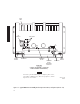
Figure 1-1 Typical MDR-8000 Hot-Standby Shelf Component Locations, and Options (Sheet 3 of 3 )
RF
SWITCH
B-SIDE
POWER
RF SWITCH
XMT
A
RCV
ANT
B
RCV
ISOLATORS
HEAT
SINK
A-SIDE
POWER
LMW-7211-SM
06/08/04
DIPLEXER
FILTER
MOUNTING
BRACKET
ISOLATOR
DIPLEXER
FILTER
REAR VIEW
(TYPICAL HOT-STANDBY 1:10 COUPLER
SINGLE ANTENNA CONFIGURATION)
Location of A and B RCV ports on diplexer filter varies,
depending on RF frequency. For some frequencies, A and
B ports reverse location.
Note