
User's Manual


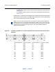


Table Of Contents

Functional operation
210
Product Information Manual
DRAFT — Internal
• Size and Type – 2, 4, 6, 8, or 10 foot parabolic; 1 or 2 foot flat panel.
− Parabolic antennas, See Table 21.
− Flat antennas, See Table 21.
• Gain and 3 dB Beamwidth
This device has been designed to operate with the antennas listed below, and having
a maximum gain of 42.5 dB. Antennas not included in this list or having a gain greater
than 42.5 dB are strictly prohibited for use with this device. The required antenna
impedance is 50 ohms.
These antennas can only be used in a fixed point-to-point configuration.
To reduce potential radio interference to other users, the antenna type and its gain
should be so chosen that the equivalent isotropically radiated power (e.i.r.p.) is not
more than that permitted for successful communication.
The antennas used for this transmitter must be installed to provide a separation
distance of at least 12 meters from all persons and must not be co-located or
operating in conjunction with any other antenna or transmitter.
Frequency Plan:
• For MPT-HL frequency plan for the 5.725 and 5.850 GHz unlicensed band,
see Figure 60.
Table 21 5.8 GHz unlicensed antenna options
PARABOLIC FLAT
MPT-HL/HLC/9558HC MPT-HL/HLC/9558HC
2 ft parabolic – 29 dB/6° 1 ft flat panel – 23 dB/9°
4 ft parabolic – 35 dB/3° 2 ft flat panel – 28 dB/3.5°
6 ft parabolic – 38 dB/2° —
8 ft parabolic – 41 dB/1.5° —
10 ft parabolic – 42.5 dB/1.2° —
Caution: Danger of public exposure to long term RF radiated energy. When using a 1 ft flat
panel antenna with a 1 watt (+30 dBm) output power, the antenna must be located in an
area that does not allow the general population access to within 12 meters (5.8 Ghz) of the
antenna.