
User guide
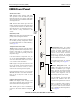

Chassis Management Module (CMM) CMM Front Panel
OmniSwitch 7700/7800 Hardware Users Guide April 2005 page 4-5
Access to the EMP
By default, only devices in the same subnet as the EMP will be able to manage the switch through that
port. To allow access to the EMP to devices outside the EMP's local network, you can create a static route
between the EMP and the network containing devices requiring access to the EMP.
To create a static route for the EMP, use the ip static-route command. The command syntax must include
the network IP address as well as the gateway address for the EMP. For example:
-> ip static-route 10.11.100.1 gateway 172.22.2.120
EMP Cable Requirements
There are specific cable type requirements (i.e., straight-through or crossover) based on the type of device
to which the EMP is connecting. Refer to the information below:
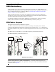
Console/Modem Port
Serial Connection to the Console/Modem Port
The console port, located on the CMM front panel, provides a serial connection to the switch and is
required when logging into the switch for the first time. By default, this female DB-9 connector provides a
DCE console connection. However, by changing the onboard jumper setting, the port can be changed to a
DTE modem connection. Refer to “Converting the Console Port to a Modem Port” on page 4-8 for more
information.
Serial Connection Default Settings
The factory default settings for the serial connection are as follows:
Modifying the Serial Connection Settings
If you wish to modify the default serial connection settings (i.e., baud rate, parity, data bits, and stop bits),
refer to the following steps.
Note. You must be connected to the switch via the console port before attempting to change serial connec-
tion settings. Otherwise, an error message will display.
1 Enter modify boot parameters at the CLI prompt. The boot prompt displays:
Boot >
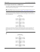
EMP to a Switch Straight-through
EMP to a Computer or Workstation Crossover
baud rate 9600
parity none
data bits (word size) 8
stop bits 1
X-ON/X-OFF enabled