
User guide


OmniSwitch 6400 Series Chassis Configurations OmniSwitch 6400 Series Chassis and Hardware Components
page 2-18 OmniSwitch 6400 Series Hardware Users Guide July 2010
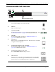
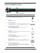
OmniSwitch 6400-P48 Rear Panel
Note. The figure shows a pre-production version of the chassis without product, safety, and compliance
information labels. All production versions of the chassis have these labels.
OS6400-P48 Rear Panel
Note . The rear panel of the OS6400-P48 contains three DB-25 power supply connectors for connecting
external 360W and 510W power supplies. One of the connectors is labeled 'Primary PS1' and two of the
connectors are labeled 'Backup PS2'. The primary power supply must be connected to the 'Primary PS1'
connector. A redundant power supply can be connected to either of the 'Backup PS2' connectors.
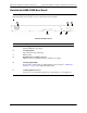
Item Description
A
Primary PS1 Power Supply Connector
DB-25 connector for required external primary power supply.
B
Redundant PS2 Power Supply Connector
DB-25 connector for optional external redundant power supply.
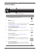
C
Grounding Block
Type LCD8-10A-L grounding lug
D
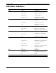
Stacking/Uplink LEDs
Provides link or traffic status for stacking/uplink connectors. Refer to “LED Status
Indicators” on page 2-20 for LED status information.
E
Stacking/Uplink Connectors
Connectors for use in stacking switches into a virtual chassis or as an uplink port
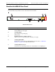
B
A
B C
E
D