INSTRUCTION MANUAL 2025 ALL MODELS PNEUDRAULIC INSTALLATION TOOL ALCOA FASTENING SYSTEMS ALCOA FASTENING SYSTEMS ALCOA FASTENING SYSTEMS ALCOA FASTENING SYSTEMS ALCOA FASTENING SYSTEMS ALCOA FASTENING SYSTEMS ALCOA FASTENING SYSTEMS ALCOA FASTENING SYSTEMS 04/02/2003 HK1006
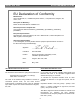
MODEL 2025 TOOL ALCOA FASTENING SYSTEMS EU Declaration of Conformity Manufacturer: Huck International, Inc., Installation Systems Division, 1 Corporate Drive, Kingston, NY, 12401, USA Description of Machinery: Model number 2025 fastener installation tool Relevant provisions complied with: Council Directive related to Machinery, (89/392/EEC), (91/368/EEC), (93/44/EEC), (93/68/EEC) European Representative: Rob Pattendon, Huck International, Ltd.
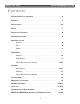
MODEL 2025 TOOL ALCOA FASTENING SYSTEMS CONTENTS EU DECLARATION OF CONFORMITY . . . . . . . . . . . . . . . . . . . . . . . . . . . . . . . . .2 CONTENTS . . . . . . . . . . . . . . . . . . . . . . . . . . . . . . . . . . . . . . . . . . . . . . . . . .3 SPECIFICATIONS . . . . . . . . . . . . . . . . . . . . . . . . . . . . . . . . . . . . . . . . . . . . .4-6 SAFETY . . . . . . . . . . . . . . . . . . . . . . . . . . . . . . . . . . . . . . . . . . . . . . . . . . . .
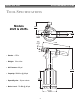
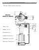
MODEL 2025 TOOL ALCOA FASTENING SYSTEMS TOOL SPECIFICATIONS Models 2025 & 2025L 3.865 98.17 ø 1.812 46.02 1.102 27.98 .906 23.02 8.366 212.51 10° • Stroke: .675 in • Weight: 5 lbs 12oz • Air Pressure: 90 psi 12.536 318.41 • Capacity: 5290 lbs @ 90 psi • Speed/Cycles: 30 per minute 5.383 136.73 • Noise Level: 75 dBA @ 90 psi 4.355 ø 110.
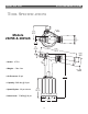
MODEL 2025 TOOL ALCOA FASTENING SYSTEMS TOOL SPECIFICATIONS Models 2025V & 2025LV ø 3.87 98.17 1.81 46.02 1.10 27.98 .91 23.02 10.18 258.67 1.240 31.5 10° • Stroke: .675 in • Weight: 5 lbs 12oz ø 2.480 62.99 • Air Pressure: 90 psi 12.54 318.41 • Capacity: 5290 lbs @ 90 psi • Speed/Cycles: 30 per minute 5.38 136.73 • Noise Level: 75 dBA @ 90 psi 4.36 ø 110.
MODEL 2025 TOOL ALCOA FASTENING SYSTEMS TOOL SPECIFICATIONS Models 2025B & 2025LB ø 3.87 98.17 1.81 46.02 1.10 27.98 .91 23.02 9.65 245.11 1.240 31.5 10° • Stroke: .675 in • Weight: 5 lbs 12oz ø 2.480 62.99 • Air Pressure: 90 psi 12.54 318.41 • Capacity: 5289 lbs @ 90 psi • Speed/Cycles: 30 per minute 5.38 136.73 • Noise Level: 75 dBA @ 90 psi 4.36 ø 110.
MODEL 2025 TOOL ALCOA FASTENING SYSTEMS SAFETY This instruction manual must be read with particular attention to the following safety guidelines, by any person servicing or operating this tool. 1 primary power supply - - as applicable, each of the sections in this manual have specific safety, and other information. 4 When repairing or operating Huck installation equipment always wear approved eye protection. Where applicable, refer to ANSI Z87.
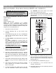
MODEL 2025 TOOL ALCOA FASTENING SYSTEMS PRINCIPLE OF OPERATION PULL PISTON SPRING DAMPER VALVE HYDRAULIC PISTON HYDRAULIC PISTON THROTTLE VALVE (RETURN POSITION) THROTTLE VALVE (PULL POSITION) Hydraulic Oil Air Pressure EXHAUST Exhaust Air AIR PISTON Fig. 1(a) Fig. 1(b) When the trigger is depressed the throttle valve moves to down position, pressurized air is directed to the bottom of the air piston, causing the piston to move upward (Fig.1a).
MODEL 2025 TOOL ALCOA FASTENING SYSTEMS PREPARATION FOR USE The Model 2025 Installation Tool is shipped with a plastic plug in the air inlet connector. The connector has 1/4-18 female pipe threads to accept the air hose fitting. Quick disconnect fittings and 1/4” inside diameter air hose are recommended. An air supply of 90 - 100 psi capable of 20 CFM must be available. Air supply should be equipped with a filter-regulator-lubricator unit. 8.
MODEL 2025 TOOL ALCOA FASTENING SYSTEMS DISASSEMBLY INSTRUCTIONS 2025 ALL MODELS ! (47). CAUTION: Care must be taken not to scratch piston rod or cylinder during removal WARNING: Be sure air hose is disconnected from tool before cleaning, or performing maintenance. Severe personal injury may occur if air hose is not disconnected. 10. Remove Bumper (34) from Gland Assembly. Unscrew Gland Assembly ( 25) with 1 3/8 socket wrench and extension bar.
MODEL 2025 TOOL ALCOA FASTENING SYSTEMS Head/handle 2025 & 2025L: (Refer to Figures 3, 4 & 14) 20. Remove piston assembly tool and spacer from piston. Rethread on the piston assembly tool only, then slide the front gland assembly off the Piston (6) (Fig. 4). 15. Unscrew End Cap (21) and remove Spring (19), Spacer (22) and Wiper Seal (23). NOTE: For 2025V please reference Disassembly of Pintail Bottle and Vacuum System procedure. 21. Remove Piston Assembly Tool from Piston (6).
MODEL 2025 TOOL ALCOA FASTENING SYSTEMS 6. Remove Spacer (22) and ORing (68) from spring side of end cap. FIG. 6 19 7. From bottle side of end cap, remove Retaining Ring (66), Wiper Housing (67), Wiper Seal (23), Washer (71) and O-Ring (69). 21 22 8. Remove the O-Rings (65) from the inside of the Adapter and Tube/Slide Assembly (70) (Fig 15). 69 71 23 67 66 68 ASSEMBLY INSTRUCTIONS 2025 ALL MODELS Head/handle 2025, 2025B, 2025L & 2025LB 2. Screw Nose Adapter (8) into Head (1) and tighten.
MODEL 2025 TOOL ALCOA FASTENING SYSTEMS 7. Install assembled components in gently from rear of tool using a press as shown in (Fig. 8). 20. Assembly O-Rings (50) on Throttle Valve (52). 14 Section CC) 8. Remove Piston Assembly Tool (123111-2 or 123111-4) and POLYSEAL Insertion / removal (121694-2025) Tool. 21. Place the tool upright on a level surface, drop Spring (49) into throttle valve bore in cylinder (35). Push Throttle Valve into cylinder. 9. Install Rear Wiper Seal (23) into End Cap (21) (Fig.
MODEL 2025 TOOL ALCOA FASTENING SYSTEMS Fill and Bleed 2025 All Models ! Equipment Required: - Shop airline with 90 - 100 psi max. - Air regulator - Fill bottle, 120337, (supplied with tool). - Large flat blade screwdriver - Optional Stall Nut 124090 or 125340 - Nose assembly - Fasteners (optional) ! Caution - All oil must be purged from tool before Fill & Bleed process. Tool stroke will be diminished if oil is aerated. Step 3 Screw fill bottle (120337) into fillport.
MODEL 2025 TOOL ALCOA FASTENING SYSTEMS MEASURING TOOL STROKE X FIG. 12 Y 2025, 2025B & 2025V Step 1 Cycle Piston all the way forward and measure X. Step 2 Cycle and hold piston back and measure Y. Step 3 Stroke = Y-X X FIG. 13 Y 2025L, 2025LB & 2025LV Step 1 Cycle Piston all the way forward and measure X. Step 2 Cycle and hold piston back and measure Y.
MODEL 2025 TOOL ALCOA FASTENING SYSTEMS ASSEMBLY DRAWING (Refer to Parts Lists on following pages) FIG. 14 A 10 11 12 14 15 16 17 9 18 8 72 19 20 21 22 23 24 (2025L 6 style) 56 55 7 (2025) 6 54 5 4 3 2 25 Timing Pin 1 34 48 73 35 A 36 53 52 37 50 47 51 38 46 39 C C 45 44 42 43 40 41 SECTION A-A 50 49 M PRESS A X FLOW 31 32 74 BAR GPM HUCK 2025 HUCK INTL,INC 1 CORP. DR. KINGSTON, N.Y. 12401 USA S/N 61 60 59 58 110 PSI 7.
MODEL 2025 TOOL ALCOA FASTENING SYSTEMS ASSEMBLY DRAWING (Refer to Parts Lists on following pages) FIG.
MODEL 2025 TOOL ALCOA FASTENING SYSTEMS PARTS LIST ITEM PART NUMBER DESCRIPTION 2025V QTY 2025LV 2025 2025L 2025LB 1 2 3 4 5 6 125736 116404-1 505496 500621 124333-1 125738 125736 116404-1 505496 500621 124333-1 125738-1 125736 116404-1 505496 500621 124333-1 125737-1 125736 116404-1 505496 500621 124333-1 125738-2 125736 116404-1 505496 500621 124333-1 125738-3 7 8 9 10 11 12 14 15 16 17 18 19 20 21 22 23 24 25 26 27 28 29 30 31 32 33 34 35 111795 123761 505817 122432 501110 500816 505818
MODEL 2025 TOOL ALCOA FASTENING SYSTEMS PARTS LIST PART NUMBER ITEM 36 37 38 39 40 41 42 43 44 45 46 47 48 49 50 51 52 53 54 55 56 57 58 59 60 61 62 63 64 65 66 67 68 69 70 71 72 73 74 DESCRIPTION 2025 2025L 2025LB 2025V 2025LV 125743 125744 507445 126941-4 504127 125750 115554-1 505420 506493 125747 500871 501458 125118 116272 507396 507164 125562-1 125751 506576 100309 505438 500779 500778 590350 590351 590347 -------------------------------------------------------------------------------------
MODEL 2025 TOOL ALCOA FASTENING SYSTEMS TROUBLESHOOTING Always check out the simplest possible cause of a malfunction first. For example, an air hose not connected. Then proceed logically, eliminating each possible cause until the cause is located. Where possible, substitute known good parts for suspected bad parts. Use TROUBLESHOOTING CHART as an aid in locating and correcting malfunction. 8. Air leaks at air Cylinder Head (45). a). Worn or damaged necessary. O-ring (46) replace ACCESSORIES 1.
---------------------------------------------------------------------------1. CHEMICAL PRODUCT/COMPANY IDENTIFICATION ---------------------------------------------------------------------------HYDROCLEAR(R) DEXRON(R) III/MERCON(R) Automatic Transmission Fluid --------------------------------------------------------------------------5.
Applicable Exposure Limits If oil mist is generated, exposure limits apply. PEL (OSHA) : 5 mg/m3, 8 Hr. TWA TLV (ACGIH) : 5 mg/m3, 8 Hr. TWA, STEL 10 mg/m3 SARA, TITLE III, 302/304 It is possible material may contain extremely hazardous substances at concentrations below 1.0% so that a large-enough spill could warrant an Emergency Release Report. --------------------------------------------------------------------------9.
HUCK FASTENERS LIMITED WARRANTIES Tooling Warranty: Huck warrants that tooling and other items (excluding fasteners, and hereinafter referred as "other items") manufactured by Huck shall be free from defects in workmanship and materials for a period of ninety (90) days from the date of original purchase.
HUCK FASTENERS Huck Acceptance is World-wide Huck Fastener maintains company offices throughout the United States and Canada with subsidiary offices in many other countries. Sales engineers and systems specialists located in your area can help in solving your fastener problems. Huck Fasteners world-wide locations: Americas Huck International, Inc. World Headquarters 3724 East Columbia Tucson, AZ 85714 800-234-4825 520-747-9898 FAX: 520-748-2142 Huck International, Inc.