
Instruction manual


MODEL 2025 TOOL ALCOA FASTENING SYSTEMS
10
DISASSEMBLY INSTRUCTIONS 2025 ALL MODELS
For component identification and Parts list refer to
Figures 14 & 15.
General
(Refer to Figures 2 & 14)
NOTE: The following procedure is for complete
disassembly of tool. Disassemble only components
necessary to replace damaged O-rings, Quad rings, Back-
up rings, and worn or damaged components. Always use
soft jaw vice to avoid damage to tool.
1. Disconnect tool from air source.
2. Unscrew Retaining Nut (7) and remove nose
assembly.
3. Unscrew Bleed Plug (55), from top of Handle/head.
Turn tool over and allow fluid to drain into container
(Fig. 10 & 14).
4. For 2025 & 2025L: Pull Pintail Deflector (24) off End
Cap (21).
For 2025B & 2025LB: By reaching through the
window of Pintail Bottle (24) remove Retaining Ring
(62) and Washer (63), then remove Pintail Bottle (24)
and Adapter (64). (Figures 14 & 15).
For 2025V & 2025LV: Please reference Disassembly
of Pintail Bottle and Vacuum System Procedure.
5. Remove Throttle Arm Pivot Screw (48) and Lever
Guard (73), and lift out Throttle Arm (53). Disconnect
ball end of Cable Assembly (2) from throttle arm.
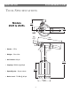
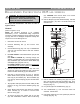
6. Hold tool in vise with bottom up. (Fig. 2) Remove
Button Head Screws (40) with 1/8 hex key. Remove
End Cap (41) and Gasket (39). Remove Muffler (42)
from end cap. Remove Spring (49) from Throttle Valve
(Fig.14).
7. Tap Cylinder Head (45) down with soft mallet (to take
pressure off ring), and remove Retaining Ring (38)
(Fig.2).
8. Screw Button Head Screws (40) back into Cylinder
Head. Carefully pry on screws to remove head.
Remove O-ring (46).
9. To remove air piston from cylinder, pull on Lock Nut
(43) with VISE-GRIPS. Remove Piston Quad Ring
(47). CAUTION: Care must be taken not to scratch
piston rod or cylinder during removal
10. Remove Bumper (34) from Gland Assembly. Unscrew
Gland Assembly ( 25) with 1 3/8 socket wrench and
extension bar.
11. Remove SPIRO-LOX Retaining Ring (30) from gland
(26), pull out Spacer (29) and POLYSEAL (28). Then
remove O-rings (31 & 27), Quad Ring (33) & Back-up
Ring (32) (Fig. 14).
12. Lift cylinder (35) from handle/head (1) (Fig. 2).
13. Turn handle/head (1) over and drain fluid into
container. Discard fluid.
14. Pull Throttle Valve (52) out of air cylinder (35). Remove
O-Rings (50) (Fig. 14).
!
WARNING: Be sure air hose is disconnected
from tool before cleaning, or performing
maintenance. Severe personal injury may
occur if air hose is not disconnected.
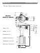
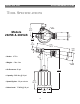
35
Timing Pin
40
41
42
38
45
46
43, 44
37
47
34
36
25
39
1
FIG. 2